
Mop with humidity regulating device

A technology of humidity adjustment and mopping, which is applied in the fields of electronic information and sanitation cleaning, can solve the problems of unable to actively control humidity and reduce efficiency, and achieve the effect of reducing frequency and improving efficiency

Inactive Publication Date: 2015-05-27
西安思创达通讯科技有限责任公司
View PDF0 Cites 7 Cited by
  • Summary
  • Abstract
  • Description
  • Claims
  • Application Information

AI Technical Summary

Problems solved by technology

[0007] The purpose of the present invention is to solve the problem that the current mop can only be repeatedly watered and then wrung out, and the humidity cannot be actively controlled, so that the process of washing the mop is repeated many times and the efficiency is reduced

Method used


Image

  • Mop with humidity regulating device

Examples


Embodiment 1

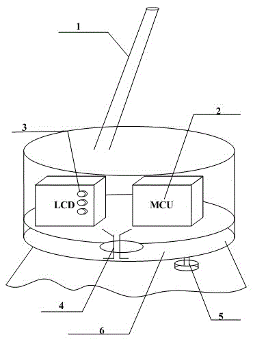
[0016] A mop with a humidity regulating device. It includes a mop shell 1, a microcontroller 2, a display and a battery 3, a valve 4, a humidity sensor 5, and a water tank 6. Microcontroller 2 is installed in the bottom right position of mop shell 1, the top of water tank 6. Microcontroller 2 is connected with display and battery 3 . Display and battery 3 are installed in the lower left position of mop shell 1. The valve 4 is installed at the bottom position of the water tank 6 . The valve 4 is connected with the display and the battery 3 . Humidity sensor 5 is connected in the bottom right of water tank 6. The humidity sensor 5 is connected with the microcontroller 2 . Water tank 6 is installed on the bottom of mop shell 1.

[0017] The water tank of the present invention has a larger volume and can store more water, so the humidity can be effectively adjusted during use, and the times of washing can be reduced. And because of the humidity sensor, it can accurately che...

Embodiment 2

[0019] The utility model relates to a mop with a humidity regulating device, the bottom water tank and the shell adopt a cylindrical structure; the bottom decontamination part adopts cloth strips. The cylindrical structure is designed to maximize the capacity while saving materials; while the cloth strip adopts the traditional design, which is economical, practical and easy to promote.

[0020] In actual use, install the battery on the present invention, set the desired humidity through the screen and the buttons next to it, and then fill the water tank with water. Then the microprocessor starts to control the valve at the bottom of the water tank to discharge a certain amount of water. When the data of the humidity sensor is transmitted to the microcontroller, the negative feedback adjustment is carried out, so as to control the humidity of the mop more accurately.

[0021] In this way, users can set the humidity they want through the buttons and the screen, and have substan...


PUM


Abstract

The invention belongs to the technical field of electronic information and environmental sanitation cleaning and specifically provides a mop with a humidity regulating device. The mop comprises a mop housing, a micro controller, a display and a battery, a valve, a humidity sensor and a water tank, wherein the micro controller is mounted on a position, above the water tank, at the lower right side of the mop housing. The micro controller is connected with the display and the battery. The display and the battery are mounted on a position at the lower left side of the mop housing. The valve is mounted on the bottom position of the water tank. The valve is connected with the display and the battery. The humidity sensor is connected at the right lower side of the water tank. The humidity sensor is connected with the micro controller. The water tank is mounted on the bottommost part of the mop housing. The mop solves the problems that an existing mop only can be repeatedly wetted and then dried, and cannot actively control the humidity, so that the mop cleaning process is repeated by many times, and the efficiency is lowered. The water tank, the valve and the humidity detecting device are mounted on the bottom of the mop, so that the problems are solved very well.

Description

technical field [0001] The invention belongs to the technical field of electronic information and environmental sanitation, and in particular relates to a mop with a humidity regulating device. Background technique [0002] With the improvement of living standards and the improvement of hygiene awareness, people are more and more fond of the hygiene of carefully cleaned rooms. And mop is subject to liking of people because it can effectively remove dust and increase humidity. [0003] The principle of the mop is to use the adsorption force of the wet cloth to absorb dust and garbage on the mop, and then move it away by hand. [0004] This just makes the mop must be constantly rinsed with water to remove dirt during the practical process, and the humidity of the floor that comes out at last is determined by the humidity of the mop, which is often difficult to control. [0005] Therefore, how to better control the humidity of the mop is to some extent an important issue when...

Claims


Application Information

Patent Timeline
Patent Type & Authority Applications(China)
IPC IPC(8): A47L13/22
Inventor 巨杰
Owner 西安思创达通讯科技有限责任公司
Learn More