Large-torque permanent magnet worm and gear transmission mechanism

A technology of transmission mechanism and worm gear, which is applied in the field of high-torque permanent magnet worm gear transmission mechanism, which can solve the problems of material loss, mechanical fatigue, short life, etc.

Inactive Publication Date: 2015-05-20
DALIAN UNIV OF TECH
View PDF3 Cites 0 Cited by
  • Summary
  • Abstract
  • Description
  • Claims
  • Application Information

AI Technical Summary

Problems solved by technology

[0002] The traditional worm gear transmission is a contact friction transmission, which has problems such as mechanical fatigue, material loss, vibration noise, etc., and the transmission efficiency is low, energy consumption is large, and the service life is short
For this reason, someone proposed a permanent magnet worm gear transmission based on the principle of a permanent magnet gear. From the patents of the permanent magnet worm gear transmission reviewed, the main problem is that the meshing area of ​​the permanent magnet worm gear is insufficient, the transmission torque is small, and the permanent magnet is fully charged. The magnetism is complex, and some permanent magnet worm gears and permanent magnets on the worm are distributed in space. When the transmission torque is large, mechanical contact or interference will occur, which will easily cause damage to the permanent magnets, and there is no overload protection function.

Method used


Image

  • Large-torque permanent magnet worm and gear transmission mechanism
  • Large-torque permanent magnet worm and gear transmission mechanism
  • Large-torque permanent magnet worm and gear transmission mechanism

Examples


Embodiment Construction

[0024] Below in conjunction with specific embodiment and accompanying drawing, the present invention is further described:

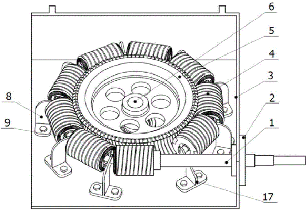
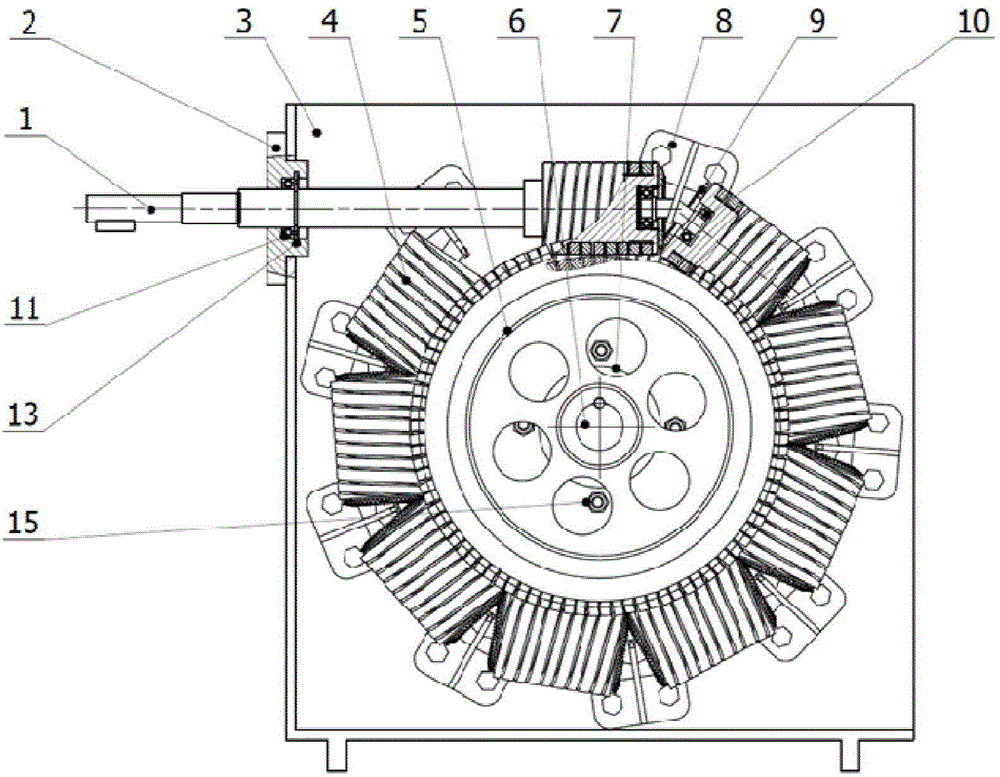
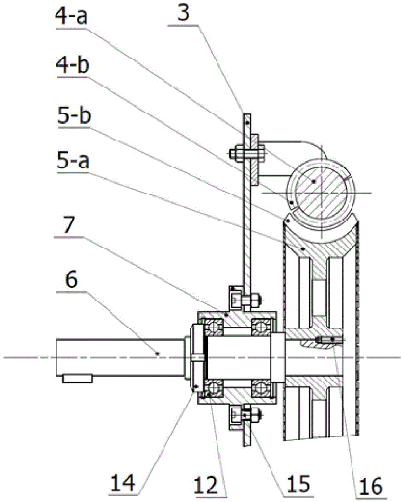
[0025] like figure 1 As shown, this permanent magnet worm gear transmission mechanism is meshed with 8 permanent magnet worms 4 and permanent magnet worm shafts 1 by a permanent magnet worm gear 5, and 8 permanent magnet worms 4 connected in series are connected end to end with the permanent magnet worm shaft 1 to connect the permanent magnets. The worm wheel 5 is surrounded, and the angle between the two permanent magnet worms 4 is about 143 degrees, such as figure 2 and image 3 As shown, the axis of the permanent magnet worm 4 coincides with the center of the outline arc of the powerful arc magnet 5-b installed on the outer edge of the permanent magnet worm wheel 5, and the permanent magnet worm wheel 5 is not in contact with the permanent magnet worm 4 and the permanent magnet worm shaft 1 .

[0026] The permanent magnet worm wheel 5 is composed ...


PUM


Abstract

The invention discloses a large-torque permanent magnetic worm and gear transmission mechanism, and aims to solve the problems of mechanical fatigue, friction loss, self-locking, vibration noise and the like in an ordinary worm and gear. A magnetic coupling wrap angle is increased in a way of meshing a plurality of permanent magnetic worms which are connected in series with a permanent magnetic worm wheel, so that the problems of low transmission torque and low power in the conventional permanent magnetic worm and gear are solved. Circular-arc-shaped strong permanent magnets of which the N-S poles are kept away are arranged on the outer edge of a wheel hub of the permanent magnetic worm wheel; a corresponding dual-wire helical groove is machined in a substrate of the permanent magnetic worm wheel according to the pitches of the circular-arc-shaped magnets on the permanent magnetic worm wheel; helical magnets of which the radial magnetic poles are reverse are arranged in parallel in the dual wire helical groove, and are meshed with the permanent magnetic worm wheel through magnetic coupling, and synchronous rotation of a plurality of permanent magnetic worms is ensured through conical gear rings and a special shaft bracket. By adopting the large-torque permanent magnetic worm and gear transmission mechanism, large-torque, non-contact and non-friction transmission can be realized, and the large-torque permanent magnetic worm and gear transmission mechanism can be taken as a transmission mechanism in the engineering fields of power machinery, traffic tools, power generation and the like.

Description

technical field [0001] The invention relates to a transmission device and its components, in particular to a high-torque permanent magnet worm gear transmission mechanism. Background technique [0002] The traditional worm gear transmission is a contact friction transmission, which has problems such as mechanical fatigue, material loss, vibration and noise, and has low transmission efficiency, high energy consumption and short life. For this reason, someone proposed a permanent magnet worm gear drive based on the principle of a permanent magnet gear. From the patent of the permanent magnet worm gear and worm drive reviewed, the main problem is that the meshing area of ​​the permanent magnet worm gear and worm gear is insufficient, the transmission torque is small, and the permanent magnet is fully charged. The magnetism is complex, and the permanent magnets on some permanent magnet worm gears and worms are spatially distributed. When the transmission torque is large, there w...

Claims


Application Information

Patent Timeline
Patent Type & Authority Applications(China)
IPC IPC(8): H02N11/00
CPCH02K49/102
Inventor 戴恒震刘向阳韩光江常海川戴智弘
Owner DALIAN UNIV OF TECH
Why Eureka
Try Eureka