
Electric smelting stirring mechanism for metal

A stirring mechanism and metal technology, applied in the field of machinery, can solve the problems affecting metal smelting, stirring force and speed are difficult to control, etc., to achieve the effects of reducing the impact, easy stirring control, and simple structure

Inactive Publication Date: 2015-05-20
WUHU XIECHENG METAL PROD
View PDF6 Cites 0 Cited by
  • Summary
  • Abstract
  • Description
  • Claims
  • Application Information

AI Technical Summary

Problems solved by technology

[0003] Aiming at the problem that in the existing metal smelting process, the stirring force and speed are not easy to control, which affects the metal smelting, the invention provides an electric metal smelting stirring mechanism. By designing a new stirring mechanism, the stirring control is easy, To achieve the purpose of reducing the impact on metal smelting

Method used


Image

  • Electric smelting stirring mechanism for metal

Examples


Embodiment 1

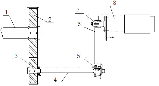
[0014] Such as figure 1 As shown, the electric metal smelting stirring mechanism includes a stirring shaft 1, a gear A2, a gear B3, a drive shaft 4, a synchronous wheel A5, a synchronous belt 6, a synchronous wheel B7, and a motor 8. The stirring shaft 1 is connected to the gear A2, so The gear A2 is meshed with the gear B3, the gear B3 is assembled on the driving shaft 4, the driving shaft 4 is connected with the synchronous wheel A5, and the synchronous wheel A5 is connected with the synchronous wheel B7 through the synchronous belt 6, Described synchronous wheel B7 is installed on the motor 8.

[0015] Described motor 8 is a stepper motor.


PUM


Abstract

The invention discloses an electric smelting stirring mechanism for metal, and belongs to the field of machines. The electric smelting stirring mechanism comprises a stirring shaft, a gear A, a gear B, a drive shaft, a synchronous wheel A, a synchronous belt, a synchronous wheel B and a motor. The stirring shaft is connected with the gear A, the gear A is meshed with the gear B, the gear B is assembled on the drive shaft connected with the synchronous wheel A, and the synchronous wheel A is connected with the synchronous wheel B through the synchronous belt, wherein the synchronous wheel B is assembled on the motor. The problem that in the prior art, in the process of metal smelting, because action force and speed of stirring are difficult to control, metal smelting is affected is solved, and the electric smelting stirring mechanism has the advantages of being simple in structure, reasonable in design and easy to manufacture.

Description

technical field [0001] The invention belongs to the field of machinery, and more specifically relates to a mechanism for stirring molten metal during metal smelting. Background technique [0002] Melting is one of the casting production processes. It is to put metal materials and other auxiliary materials into the heating furnace for melting, and then quench and temper, so that the materials in the furnace undergo certain physical and chemical changes, and produce crude metal or metal enrichment and Pyrometallurgical process of slag. During the smelting process, it is often necessary to stir the metal solution to promote the mixing of different components and speed up the reaction speed, which has become an indispensable part of metal smelting. However, in the specific operation process, due to the large force required for stirring, and the speed of stirring is not easy to control, it will have a certain impact on metal smelting. Contents of the invention [0003] Aiming...

Claims


Application Information

Patent Timeline
Patent Type & Authority Applications(China)
IPC IPC(8): F27D27/00
Inventor 程迎春
Owner WUHU XIECHENG METAL PROD
Learn More