
A Hall Thruster Magnetic Circuit Structure

A Hall thruster and magnetic circuit technology, applied in the field of plasma, can solve the problems of low radial magnetic field axial gradient, low magnetic field gradient, poor heat dissipation effect, etc., and achieve the effect of improving magnetic field gradient, reducing difficulty and improving life.

Active Publication Date: 2017-10-13
LANZHOU INST OF PHYSICS CHINESE ACADEMY OF SPACE TECH
View PDF4 Cites 3 Cited by
  • Summary
  • Abstract
  • Description
  • Claims
  • Application Information

AI Technical Summary

Problems solved by technology

The main problems of this magnetic circuit structure are: (1) The heat dissipation effect is poor, and the heat generated by the anode between the inner and outer magnetic shields cannot be well radiated from the magnetic shield wall to the surroundings, which will bring some difficulties in thermal design
(2) The magnetic field gradient is low, and the axial gradient of the radial magnetic field in the discharge channel between the inner and outer magnetic shields is low, resulting in low ionization efficiency of the working gas in the channel

Method used


Image

  • A Hall Thruster Magnetic Circuit Structure
  • A Hall Thruster Magnetic Circuit Structure
  • A Hall Thruster Magnetic Circuit Structure

Examples


Embodiment Construction

[0022] The present invention will be described in detail below with reference to the accompanying drawings and examples.

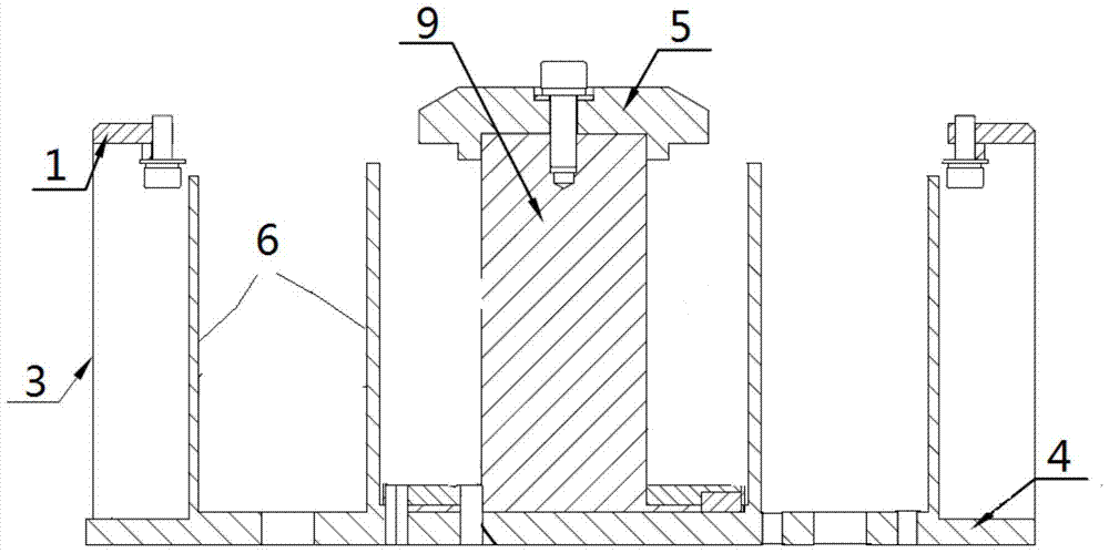
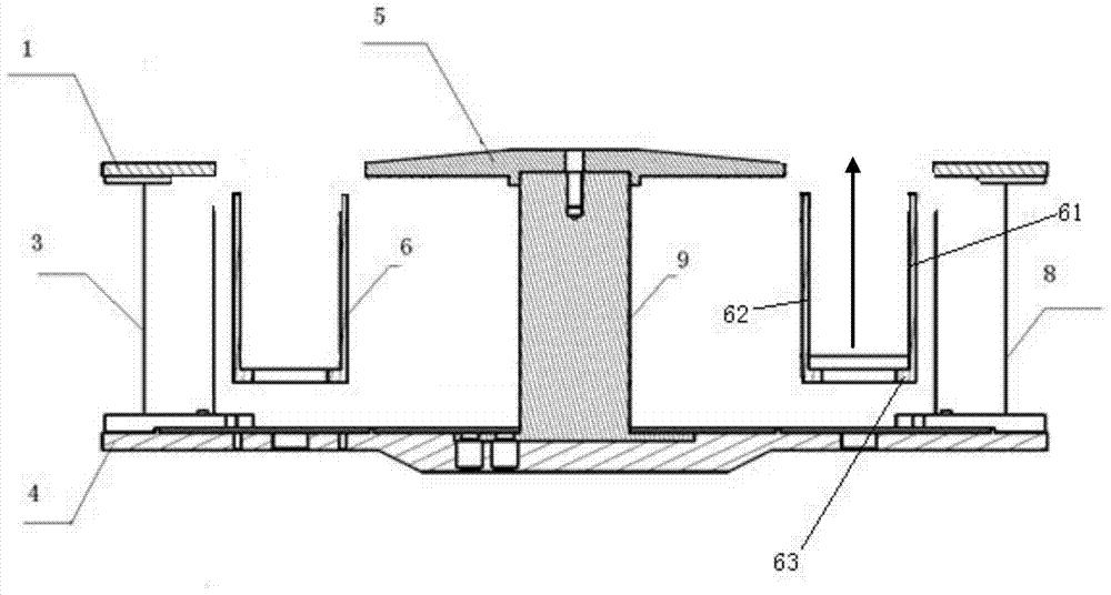
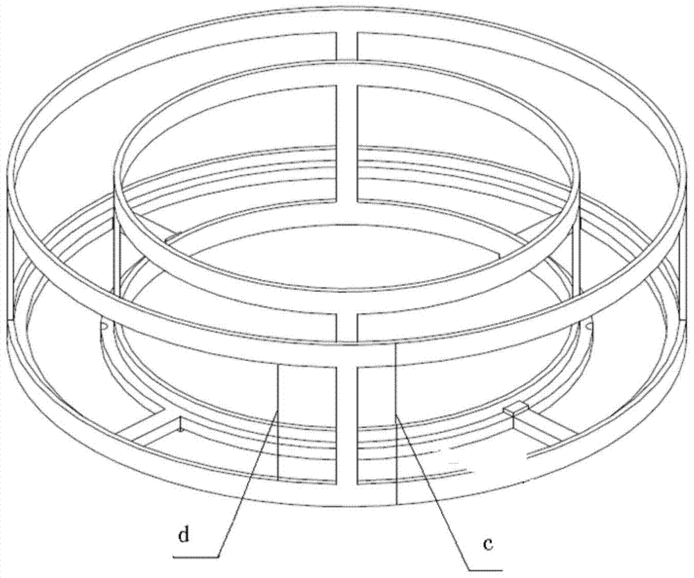
[0023] A kind of Hall thruster magnetic circuit structure of the present invention, as Figure 2-4 As shown, it includes an outer pole shoe 1, an outer ceramic ring, an outer iron core 3, a magnetic base 4, an inner pole shoe 5, a magnetic shield 6, an inner ceramic ring and an inner magnet 9, wherein the magnetic shield 6 includes an outer magnetic shield 61 and Inner magnetic screen 62, and the magnetic screen base 63 that is fixed on the bottom of the cavity formed by outer magnetic screen 61 and inner magnetic screen 62, there is a gap between the magnetic screen base 63 and the magnetic conduction base 4; the outer magnetic screen 61, the inner magnetic screen 62 and the magnetic shield base 63 respectively have a plurality of openings.

[0024] The heat dissipation efficiency in the channel can be improved through the opening, that is, the heat gene...


PUM


Abstract

The invention discloses a Hall thruster magnetic circuit structure. By forming holes in an outer magnetic screen, an inner magnetic screen and a magnetic screen base and reserving a gap between the magnetic screen base and a magnetic conductive base, the cooling efficiency of a Hall thruster discharge channel is improved, and the design difficulty of a Hall thruster can be lowered; by optimizing the parameters of the magnetic screens and particularly the sizes of the fan-shaped holes, the gradient of the magnetic field in the discharge channel is improved, and therefore the electron utilization rate and ionization efficiency are increased; meanwhile, by optimizing the areas of the fan-shaped holes, the maximum value of the radial component of the magnetic field goes beyond the upper ends of the magnetic screens, the corrosion sputtering effects of ions on a ceramic inner ring and a ceramic outer ring are reduced to the minimum, and therefore the service life of the Hall thruster is prolonged to the maximum extent.

Description

technical field [0001] The invention relates to the fields of aerospace technology and low-temperature plasma technology, in particular to a magnetic circuit structure of a Hall thruster. Background technique [0002] As an advanced space electric propulsion technology, Hall electric propulsion has the advantages of high thrust density, simple system composition, high reliability, and low launch cost, and has become one of the most widely used space electric propulsion devices. The main factor affecting the comprehensive performance of the Hall thruster is the magnetic field distribution in the discharge channel, and the magnetic field distribution depends on the magnetic circuit composition of the Hall thruster. The magnetic field in the discharge channel formed by the ideal magnetic circuit structure should have a sufficiently large axial gradient of the radial component. The position of the maximum value of the radial component is reasonable to reduce the corrosion and s...

Claims


Application Information

Patent Timeline
Patent Type & Authority Patents(China)
IPC IPC(8): F03H1/00
CPCF03H1/0081F03H1/0075
Inventor 杨乐郭宁贾艳辉陈娟娟
Owner LANZHOU INST OF PHYSICS CHINESE ACADEMY OF SPACE TECH
Learn More