
A rodless oil production device driven by a permanent magnet linear motor in the well

A permanent magnet linear motor and rodless oil production technology, which is applied in the direction of machines/engines, production fluids, earthwork drilling and production, etc., can solve the problems of increased crude oil production costs, increased maintenance workload, and reduced efficiency, so as to reduce operational safety risk, solve the eccentric wear of the rod tube, and eliminate the effect of stroke loss

Active Publication Date: 2017-07-14
PETROCHINA CO LTD
View PDF11 Cites 1 Cited by
  • Summary
  • Abstract
  • Description
  • Claims
  • Application Information

AI Technical Summary

Problems solved by technology

But it also has some deficiencies: first, there is an inherent eccentric wear problem between the sucker rod and the tubing, and this problem becomes more and more serious with the increase of water cut in the oil field, the deepening of the pump hanging and the increase of special trajectory wells. more serious
Secondly, too many transmission links, overcoming the weight and elastic deformation of the sucker rod itself will consume a part of power, which will eventually lead to a decrease in the efficiency of the rod pump system of the pumping unit, an increase in maintenance workload, and an increase in the cost of crude oil extraction

Method used


Image

  • A rodless oil production device driven by a permanent magnet linear motor in the well
  • A rodless oil production device driven by a permanent magnet linear motor in the well
  • A rodless oil production device driven by a permanent magnet linear motor in the well

Examples


Embodiment Construction

[0015] Taking a rodless oil production device driven by a downhole permanent magnet linear motor as an example, the present invention will be described in detail.

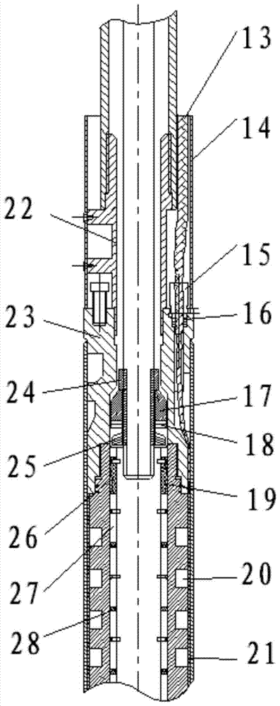
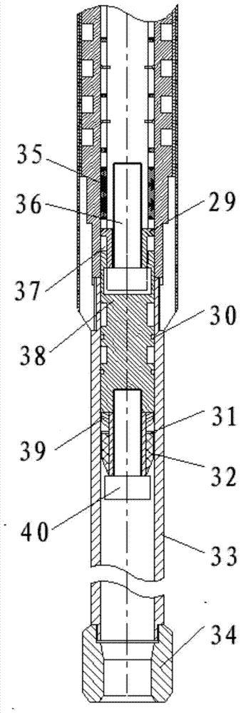
[0016] refer to figure 1 , the plunger 1 of the pull-down pump is connected to the pull rod of the motor through a conversion joint 8 with pins, the lower outer pipe of the pull-down pump is connected to the front piston collar 2 of the motor, the upper collar of the pull-down pump is connected to the tail end of the oil pipe, and the oil pipe, pull-down The pump and the downhole linear motor are lowered into the well to a predetermined depth.

[0017] The front sand control piston 9 is connected with the connecting shaft 7 by the upper piston nut 3 and the lower piston nut 11 at both ends, and the front sand control piston 9 is equipped with a sand control packing 4 and a dynamic seal 10, which jointly play a role in sealing the motor.

[0018] The front piston tube 6 is covered with a guide tube 5, which is fixe...


PUM


Abstract

The invention relates to a rodless oil extraction system driven by an underground permanent magnet linear motor. The rodless oil extraction system is composed of a front piston pipe, magnetic steel and a tail pipe. The front piston pipe is located at the uppermost end of the system and plays the roles of balancing pressure difference and preventing sand; the magnetic steel is located in the middle of the system, and the magnetic steel is powered by a cable to generate magnetic pumping so as to drive a rotor to linearly move in a reciprocating mode; the tail pipe is located at the lower end of the system and plays the roles of limiting the rotor and preventing sand for the motor; a pull-down oil well pump barrel is connected with the front piston pipe in a threaded mode, a pull-down oil well pump plunger and a motor pull rod are connected through a conversion connector with a pin, a pull-down oil well pump upper coupling is connected with an oil tube, an electronic rotor drives the pull-down oil well pump plunger to pump oil, and crude oil enters the oil tube from the pump barrel. According to the rodless oil extraction system, oil extraction without a pumping rod is achieved, and the rod pipe eccentric wear problem which can not be solved in a directional well is solved fundamentally; zero transmission from the motor to an oil well pump is achieved, stroke loss is eliminated, pumping efficiency of the oil well pump and system efficiency are improved, and operation safety risks are reduced.

Description

technical field [0001] The invention is a rodless oil production system driven by a downhole permanent magnet linear motor designed for the rodless oil production technology in an oil field. It is suitable for directional wells, inclined wells and other oil production wells prone to eccentric wear of rods and tubes, and belongs to the downhole operation tool technology of the oil and gas industry. field. Background technique [0002] In the current mechanical oil recovery method, the rod pump lifting system of the pumping unit occupies a dominant position due to its simple structure, mature technology, reliability and durability, and wide adaptability, accounting for about 90% of the number of artificially lifted wells. But it also has some deficiencies: first, there is an inherent eccentric wear problem between the sucker rod and the tubing, and this problem becomes more and more serious with the increase of water cut in the oil field, the deepening of the pump hanging and ...

Claims


Application Information

Patent Timeline
Patent Type & Authority Patents(China)
IPC IPC(8): E21B43/00F04B47/00
CPCE21B43/128F04B47/00
Inventor 杨海涛朱天寿慕立俊曾亚勤黄伟甘庆明李明辛宏张磊韩二涛
Owner PETROCHINA CO LTD
Learn More