Crane supporting leg operating mechanism and crane with same
A control mechanism, crane technology, applied in cranes, bottom support structures, hoisting equipment braking devices, etc., can solve the problems of low safety, overturning of the whole vehicle, etc., and achieve the effect of high safety
Active Publication Date: 2015-05-20
ZOOMLION HEAVY IND CO LTD
View PDF10 Cites 0 Cited by
- Summary
- Abstract
- Description
- Claims
- Application Information
AI Technical Summary
Problems solved by technology
[0002] At present, the operating handle in the outrigger control mechanism of the crane is rigidly connected to the valve core in the valve, that is to say, the valve core and the operating handle move synchronously. When
Method used
View moreImage
Smart ImageViewing Examples
Examples
 PUM
 Abstract
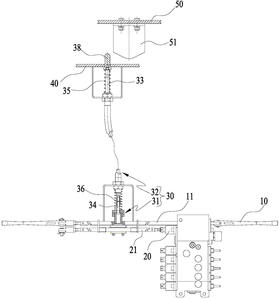
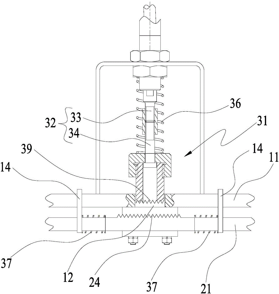
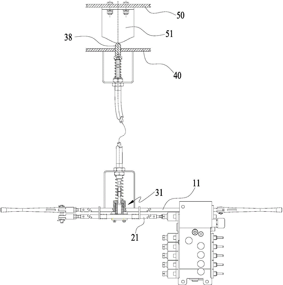
The invention provides a crane supporting leg operating mechanism and a crane with the same. The crane supporting leg operating mechanism comprises an operating handle (10), and an operating valve (20) with a valve core and also comprises an operating connecting rod (11), a valve core connecting rod (21) and a locking structure (30), wherein the operating connecting rod (11) extends in the first direction; the operating handle (10) drives the operating connecting rod (11) to move in the first direction; the valve core connecting rod (21) drives the valve core to move; the locking structure (30) comprises a locking piece (31); the locking piece (31) has a drive effectiveness state and a drive failure state; when the locking piece (31) is positioned in the drive effectiveness state, the valve core connecting rod (21) and the operating connecting rod (11) synchronously move in the first direction; and when the locking piece (31) is positioned in the drive failure state, the operating connecting rod (11) cannot drive the valve core connecting rod (21) to move in the first direction. The technical scheme of the invention has high safety.
Description
technical field [0001] The invention relates to the technical field of engineering machinery, in particular to a crane outrigger operating mechanism and a crane having the same. Background technique [0002] At present, the operating handle in the outrigger control mechanism of the crane is rigidly connected to the valve core in the valve, that is to say, the valve core and the operating handle move synchronously. When someone touches the operating handle unintentionally, it will cause the danger of the whole vehicle tipping over. It can be seen from the above that the safety of the existing crane outrigger operating mechanism is relatively low. Contents of the invention [0003] The present invention aims to provide a crane outrigger operating mechanism with higher safety and a crane with the same. [0004] In order to achieve the above object, according to one aspect of the present invention, a crane outrigger control mechanism is provided, including: a control handle;...
Claims
Login to View More Application Information
Patent Timeline
 IPC IPC(8): B66C5/00
CPCB66C5/00B66C2700/00
Inventor 陈华林彭友谊程映球
Owner ZOOMLION HEAVY IND CO LTD
- R&D Engineer
- R&D Manager
- IP Professional
- Industry Leading Data Capabilities
- Powerful AI technology
- Patent DNA Extraction
Learn More Browse by: Latest US Patents, China's latest patents, Technical Efficacy Thesaurus, Application Domain, Technology Topic, Popular Technical Reports.
© 2024 PatSnap. All rights reserved.Legal|Privacy policy|Modern Slavery Act Transparency Statement|Sitemap|About US| Contact US: help@patsnap.com


