Micro milling control system based on rotating laser beam mechanism

A control system and a technology of rotating beams, applied in the fields of laser milling and design laser processing, can solve the problems of surface quality damage of surface recast layer, excessive surface roughness of milling surface, restricting research work, etc.

Inactive Publication Date: 2015-05-20
BEIJING UNIV OF TECH
View PDF7 Cites 3 Cited by
  • Summary
  • Abstract
  • Description
  • Claims
  • Application Information

AI Technical Summary

Problems solved by technology

However, problems such as excessive surface roughness of the milled surface and damage to the surface quality of the surface recast layer restrict the further development of the research work.

Method used


Image

  • Micro milling control system based on rotating laser beam mechanism
  • Micro milling control system based on rotating laser beam mechanism
  • Micro milling control system based on rotating laser beam mechanism

Examples


Embodiment Construction

[0017] The present invention will be described in detail below in conjunction with the accompanying drawings and specific embodiments. The following exemplary embodiments and descriptions of the present invention are used to explain the present invention, but are not intended to limit the present invention.

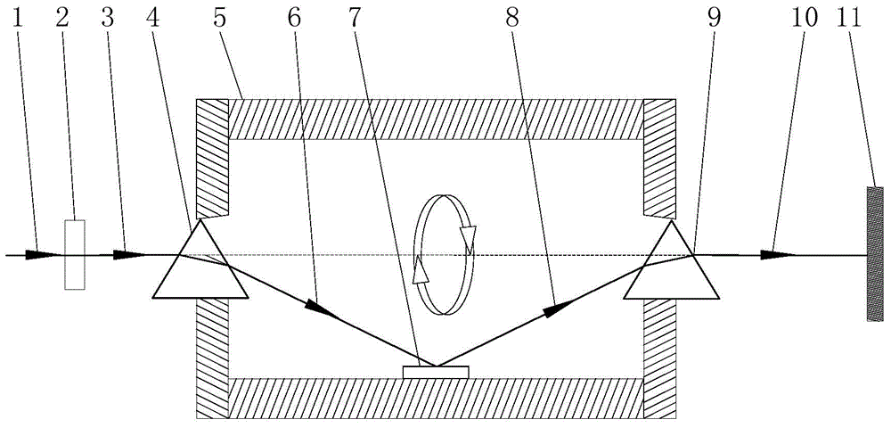
[0018] figure 1 Schematic diagram of how the optical path works for a rotating beam. It can be seen from the figure that the optical system is mainly composed of a focusing lens 2, two mirrors 4 and 9 with a deflection angle of 60°, and a plane mirror 7.

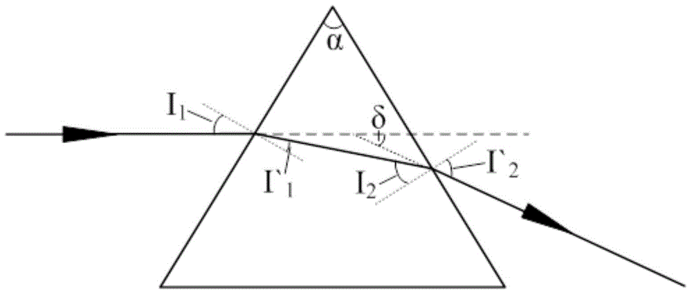
[0019] Select two triangular mirrors whose deflection angle is α=60°. The Mitsubishi mirror is ultraviolet optical quartz glass (JGS1), and its refractive index n=1.503 for ultraviolet light with a wavelength of 248 nanometers. figure 2 It is a schematic diagram of the refraction of light beams in a single triangular mirror. According to the refraction process of the light beam in the triangular mirror, sin' 1 =n s...


PUM

PropertyMeasurementUnit
lengthaaaaaaaaaa
radiusaaaaaaaaaa
thicknessaaaaaaaaaa

Abstract

The invention discloses a micro milling control system based on a rotating laser beam mechanism. The micro milling control system comprises a horizontal laser beam, a focusing module and a rotating beam module. An optical element of an optical rotating beam module mechanism comprises two triple prisms with the deflection angle of 60 degrees, a plane mirror and a rotating barrel. The two triple prisms are symmetrically fixed to the two ends of a center shaft of the rotating barrel. The plane mirror is fixed to the middle of the inner wall of the rotating barrel. Horizontal light irradiates in the center shaft direction of the rotating barrel and reaches the plane mirror after being deflected by the first triple prism. The light is emitted through the second triple prism after being reflected by the plane mirror. In the acting process unit time, light spots acting on the fixed unit area are distributed more evenly through the rotating of the light spots, the laser milling removing rate is increased, and a better surface machining quality is obtained. Meanwhile, a mask in a certain shape can be machined on the rotating beam, the shape of a cutter is simulated, rotating is carried out along with the beam, and the milling purpose is achieved.

Description

Technical field: [0001] The invention is designed in the field of laser processing, specifically in the fields of laser milling and the like. Background technique: [0002] Laser processing as a modern precision processing method The essence of laser milling is to remove material through the thermal action between the laser beam and the workpiece. Foreign scholars use laser beams with short pulse width and high peak power for milling and forming, and the removal efficiency is relatively low, which cannot meet the needs of mass production. Domestic scholars have tried high-efficiency milling and forming experiments on brittle materials such as ceramics, hard alloys, and single crystal silicon using lasers with long pulse widths and low repetition frequencies to meet the production needs of large-scale parts, but the surface roughness of the milling surface is too high. Problems such as large and surface recasting layer damage to surface quality restrict the further developme...

Claims


Application Information

Patent Timeline
Patent Type & Authority Applications(China)
IPC IPC(8): B23K26/36B23K26/066
CPCB23K26/36B23K26/0643B23K26/0648B23K26/0652
Inventor 陈涛朱航欧梁晓莉
Owner BEIJING UNIV OF TECH
Why Eureka
Try Eureka