
A combined method for deep desulfurization of liquefied gas

A combined method and deep desulfurization technology, applied in chemical instruments and methods, separation methods, gas fuels, etc., can solve problems such as insufficient oxidation, large lye consumption, and reduced extraction capacity, and achieve cleanliness and deep desulfurization The effect of high height and small footprint

Active Publication Date: 2017-08-04
PETROCHINA CO LTD
View PDF3 Cites 1 Cited by
  • Summary
  • Abstract
  • Description
  • Claims
  • Application Information

AI Technical Summary

Problems solved by technology

[0003] (1) The oxidation in the regenerative oxidation tower is not complete, and the oxygen utilization rate is generally only 10-15%. Most of the oxygen only plays the role of fully mixing the gas and liquid and blowing off the disulfide, resulting in insufficient oxidation, and the sodium mercaptide has no Complete conversion to disulfide, a large amount of unoxidized sodium mercaptide in the regenerated lye inhibits the reaction between mercaptan and sodium hydroxide in the liquefied gas, resulting in a decrease in extraction capacity;
[0004] (2) Part of the disulfides produced by oxidation exist in the regenerated lye in the state of microemulsion. The separation of disulfide and lye is not complete, and the settling time of some devices is not enough to cause poor separation effect. high substance content;
The existing technology has taken a solution to this problem, but the control effect is not ideal, the sulfur content of the circulating lye is high, the lye consumption is large, the desulfurization depth of the liquefied gas is not enough, and disulfide is easy to produce secondary pollution

Method used


Image

  • A combined method for deep desulfurization of liquefied gas

Examples


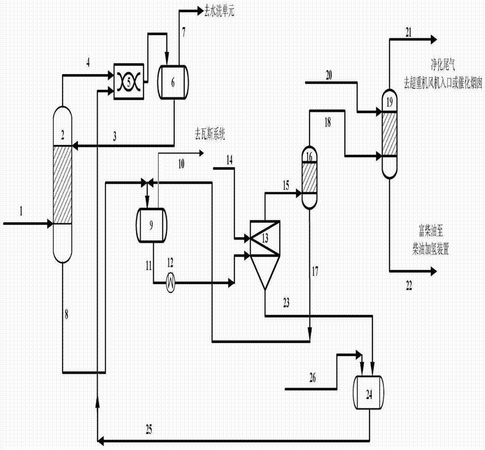
Embodiment

[0027] In the lye regeneration scale-up test with 50L / h lye treatment capacity, the lye regeneration test and the exhaust gas absorption test were carried out at the same time. In the lye regeneration test, the gas-liquid volume ratio ranges from 1 to 1500:1, and the reaction temperature is 20 to 70°C. In the exhaust gas absorption test, the diesel flow rate is 0.5~5L / h, and the reaction temperature is 20~40℃.

[0028] The lye is introduced into the heating tank from the storage tank, and after heat exchange with steam, it is pumped into the supergravity reactor, and the air is sent into the supergravity reactor by the fan. Air and waste lye are mixed in the overweight machine, the tail gas is separated by the liquid trap and then enters the absorption device. After regeneration, the lye is sampled and stored in a 1m3 barrel. The lye flow is controlled by the rotameter and the bypass valve, the air flow is controlled by the rotameter, and the speed of the overweight machine i...


PUM


Abstract

The invention relates to a combination method for deep desulfurization of liquefied gas; the liquefied gas is fed into an extraction tower, and is contacted with incoming lye in countercurrent, and the desulfurized liquefied gas and regenerated lye enter a static mixer to mix for second-stage extraction, and the mixed liquid is liquefied The gas-alkali-liquid separation tank is separated, the liquefied gas is sent to be washed with water, the uncooked alkali solution flowing out from the bottom of the extraction tower enters the flash tank, the residual liquefied gas is discharged from the top of the tank and sent to the gas system, and the uncooked solution obtained at the bottom of the tank is heated After that, it enters the supergravity reactor and reacts with non-purified wind. The tail gas discharged from the supergravity reactor is removed from the lye by the coalescer and sent back to the flash tank. The purified tail gas is returned to the supergravity reactor for recycling, and the rich diesel oil discharged from the bottom of the tower is sent to the diesel hydrogenation unit, and the regenerated lye obtained is recycled; this method has deep desulfurization depth, high quality regenerated lye, simple and reliable equipment, and low cost. The discharge of three wastes is less, and the whole process meets the requirements of environmental protection.

Description

technical field [0001] The invention relates to a liquefied gas desulfurization process, in particular to a combined process of removing sulfur-containing components in liquefied gas by using alkali liquor, realizing alkali liquor regeneration and reducing pollutant discharge. Background technique [0002] With the acceleration of the formulation and promotion of the National V gasoline standard, the contradiction between the reduction of the sulfur content of hydrogenated gasoline and the insufficient octane number gradually emerged. MTBE is a high-octane additive component of gasoline. The sulfur content of 19 sets of oil refining MTBE units of PetroChina is generally 100-400ppm, which is difficult to meet the national V gasoline standard (sulfur content is less than 10μg / g). The study found that the main reason for the excessive sulfur content in MTBE was the accumulation of C4 sulfides in the raw material mixture, and these sulfides came from the regeneration unit of liq...

Claims


Application Information

Patent Timeline
Patent Type & Authority Patents(China)
IPC IPC(8): B01D53/78B01D53/48B01D53/96B01D53/14C10L3/12
Inventor 王苑高飞周华群胡雪生李潇董卫刚张兆前李玮陈静李文琦何涛波
Owner PETROCHINA CO LTD
Learn More