A multi-band dielectric resonance mobile phone terminal antenna

A technology of dielectric resonance and mobile phone terminals, which is applied in the direction of resonant antennas, antennas, antenna supports/installation devices, etc., can solve the problem that it is difficult to meet the requirements of flexible and diverse antenna shape design, light and thin volume, narrow bandwidth and multi-band communication broadband Requirements, unable to meet multiple communication frequency bands at the same time, etc., to achieve the effect of good promotion and application prospects, light weight, and flexible design

Active Publication Date: 2018-05-15
BEIJING UNIV OF POSTS & TELECOMM
View PDF7 Cites 0 Cited by
  • Summary
  • Abstract
  • Description
  • Claims
  • Application Information

AI Technical Summary

Problems solved by technology

[0003] The main technologies of traditional terminal antennas include: 1) Inverted F antenna: simple structure, narrow bandwidth cannot meet the requirements of current communication broadband multi-band
2) Planar inverted F antenna (PIFA): It can increase the bandwidth of the antenna, but it cannot meet the requirements of multiple communication frequency bands at the same time. The section is large, and the bandwidth is greatly affected by the size of the ground
Based on the above technologies, the existing antennas are mainly divided into three-dimensional antennas and two-dimensional planar printing antennas. However, the three-dimensional antennas have the defects of large size and narrow bandwidth. requirements
Although the two-dimensional planar printed antenna achieves light and thin volume, it has defects such as complex structure, not easy to adjust, and high cost. Therefore, the design is small in size, simple in structure, and low in cost, which can meet the requirements of multi-mode The mobile phone antenna required by the frequency band is the research direction of the future terminal antenna

Method used


Image

  • A multi-band dielectric resonance mobile phone terminal antenna
  • A multi-band dielectric resonance mobile phone terminal antenna
  • A multi-band dielectric resonance mobile phone terminal antenna

Examples


Embodiment Construction

[0020] In order to make the object, technical solution and advantages of the present invention clearer, the present invention will be described in further detail below in conjunction with specific embodiments and with reference to the accompanying drawings.

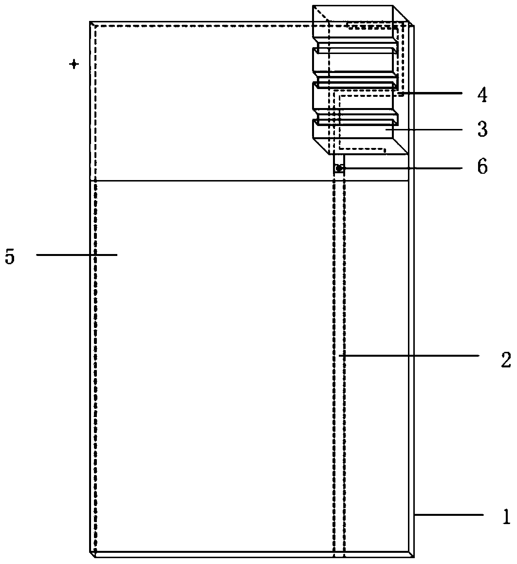
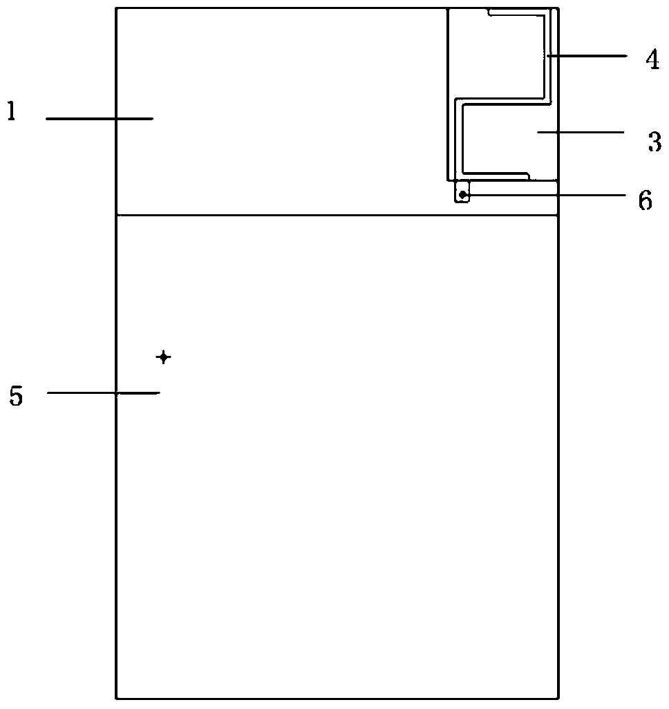
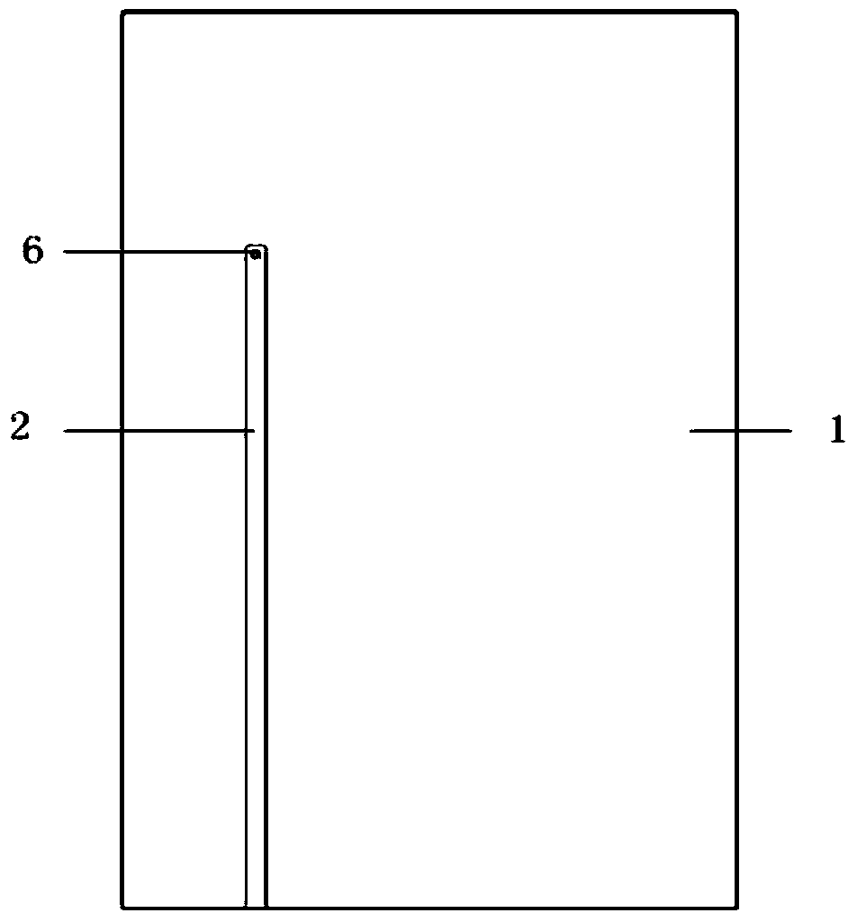
[0021] see below figure 1 , figure 2 and image 3 , which mainly introduces the structural composition of an embodiment of the multi-band dielectric resonance mobile phone terminal antenna of the present invention.

[0022] Such as figure 1 As shown, the antenna includes: as figure 1 As shown, the antenna includes: a dielectric plate 1, a feeding microstrip line 2 located on the opposite side of the dielectric plate 1, a rectangular dielectric 3 with a high dielectric constant located at a corner of the front side of the dielectric plate, and a rectangular dielectric 3 located on the bottom surface of the rectangular ceramic dielectric The multi-branch monopole 4, the printed reference ground 5 located under the rect...


PUM


Abstract

The invention discloses a multi-band dielectric resonance cell phone terminal antenna; the multi-band dielectric resonance cell phone terminal antenna comprises a rectangular ceramic dielectric medium (3) with a groove and a high dielectric constant, a multi-branch monopole (4), a dielectric board (1), a feed microstrip line (2), a printed ground (5) and a via hole (6). The antenna structure is characterized in that the use of the multi-branch monopole excite the rectangular dielectric medium with high dielectric constant, the electric field distribution in the medium is changed to make the medium generate a multi-mode resonance, thus achieving the requirements of the multi-mode multi-band of the terminal antenna, meanwhile, the dielectric medium is added with a groove, thus the radiation area of the dielectric medium can be increased as well as effectively reducing the weight of the antenna, thereby improving the radiation efficiency of the antenna. The multi-band dielectric resonance cell phone terminal antenna is characterized in small size, light weight, simple structure, wide working band, and high radiation efficiency. The multi-band dielectric resonance cell phone terminal antenna is low in manufacturing cost, simple in structure, easy to machining and integrate, can simultaneously meet the communication standards of 2G, 3G and 4G; and the multi-band dielectric resonance cell phone terminal antenna has a good popularization and application foreground.

Description

technical field [0001] The invention relates to the technical field of communication antennas, in particular to a multi-band dielectric resonance mobile phone terminal antenna. Background technique [0002] With the rapid development of wireless communication technology, communication methods and communication standards are gradually increasing, and the utilization of frequency resources is getting higher and higher. The development of the communication industry can be described as unstoppable, and terminal equipment has become the fastest-growing communication product. As the key equipment of the terminal system, the antenna is an indispensable part of it. In the 4G era, higher standards and requirements are put forward for the terminal antenna. The coexistence of various wireless communication technologies and the adoption of different network standards in different countries jointly determine the quality of mobile communication. Terminals need to be compatible with differ...

Claims


Application Information

Patent Timeline
Patent Type & Authority Patents(China)
IPC IPC(8): H01Q9/04H01Q1/24H01Q5/50
Inventor 刘元安苏明刁一恒黎淑兰于翠屏吴永乐王卫民
Owner BEIJING UNIV OF POSTS & TELECOMM
Why Eureka
Try Eureka