Antenna, receiving and transmitting device and electronic device
A technology for electronic equipment and antennas, applied in antenna support/mounting devices, foldable/stretchable loop antennas, structural forms of radiation elements, etc., can solve the problem of space occupied by antenna structures, prone to breakage, interference from external vibrations, etc. problem, achieve the effect of reducing the occupied space and improving portability
- Summary
- Abstract
- Description
- Claims
- Application Information
AI Technical Summary
Problems solved by technology
Method used
Image
Examples
Embodiment 1
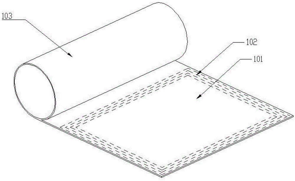
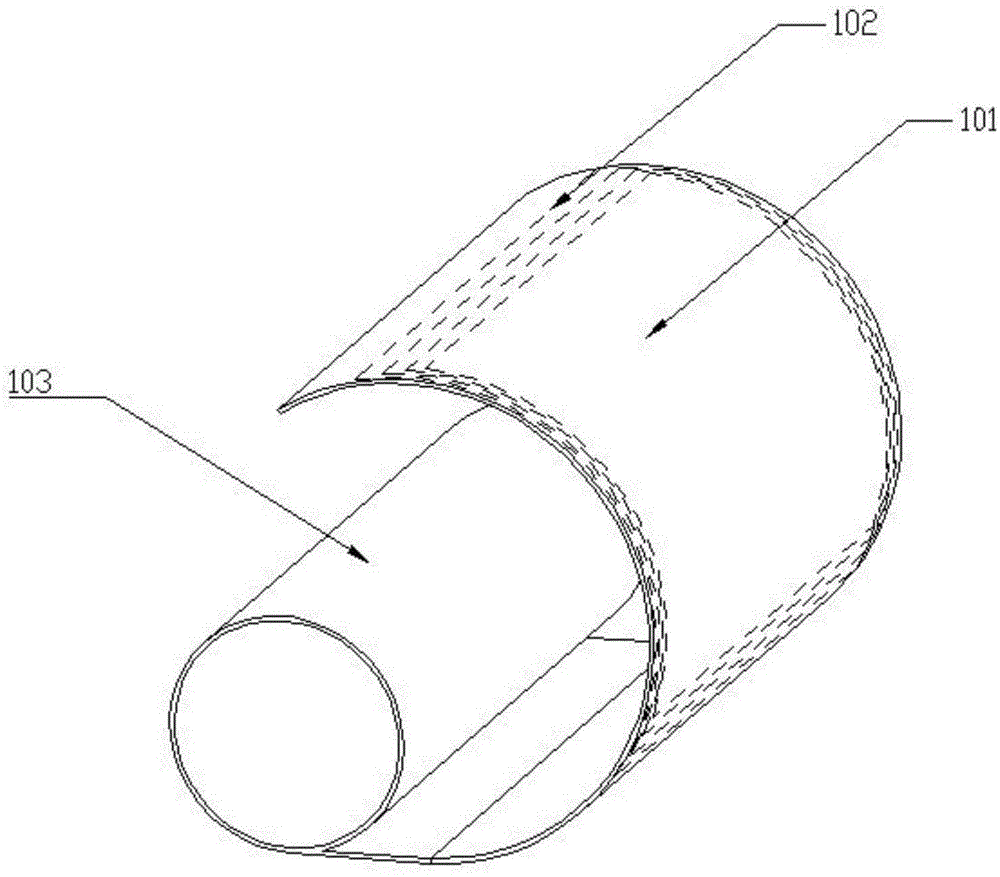
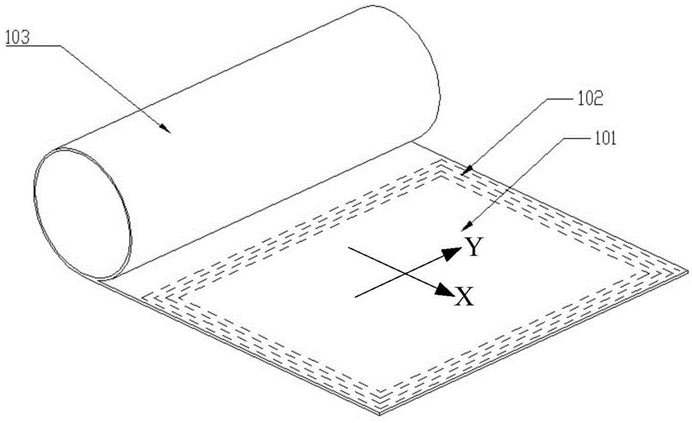
[0031] like figure 1 , 2 As shown in and 3, only its structure is illustrated to illustrate its principle, and the actual structure can be designed by those of ordinary skill in the art.
[0032] like figure 1 , 2 As shown in and 3, this embodiment provides an antenna, including: a flexible bearing part 101 and a flexible coil 102, the flexible coil 102 is arranged on the flexible bearing part 101, wherein the flexible bearing part 101 can be expanded or rolled, and In the unfolded state, the flexible bearing part 101 is planar.
[0033] Optionally, the carrying part can adopt one of the following structures, the carrying part can adopt a flexible material structure, and the flexible material structure is a structure composed of flexible and deformable materials as a whole; the carrying part can adopt a spliced structure , the splicing structure is a structure formed by splicing a plurality of hard units, and the adjacent hard units are fixed and spliced by flexible an...
Embodiment 2
[0073] This embodiment provides a transceiver device, including: a circuit and the antennas of the various implementations described in Embodiment 1. The circuit is electrically connected to the antenna, and data is transmitted and received through the antenna.
[0074] In a specific application, the circuit can provide driving for the antenna, so that the antenna has the function of data transmission and reception.
[0075] In an optional implementation of the embodiment of the present invention, the transceiver device may further include: an interface, where the interface is electrically connected to a circuit.
[0076] Through this interface, the transceiver device can be connected to an external electronic device, and the circuit processes (or does not process) the electromagnetic signal received by the antenna and sends it to the electronic device, and receives the signal that the electronic device needs to send. may not be processed) and sent to the antenna for external ...
Embodiment 3
[0080] This embodiment provides an electronic device, including the above-mentioned transceiver device.
[0081] In a specific application, the electronic device includes: a card reader. Alternatively, the electronic device may also be other electronic products, for example, a card.
[0082] In an optional solution of this embodiment, a flexible card reader is provided. The flexible card reader does not contain a support shaft and is a flexible integrated structure. Specifically, it can be one of the following structures:
[0083] 1. The carrying part can adopt a splicing structure. The splicing structure is a structure formed by splicing a plurality of narrow pieces, and the adjacent narrow pieces are fixed and spliced by flexible, flexible and deformable connecting parts or magnetic adsorption parts. The carrying part is 101 It is spliced by multiple parallel narrow pieces, and the adjacent narrow pieces are fixed and spliced by flexible and deformable connecting part...
PUM
 Abstract
Description
Claims
Application Information
 - Generate Ideas
- Intellectual Property
- Life Sciences
- Materials
- Tech Scout
- Unparalleled Data Quality
- Higher Quality Content
- 60% Fewer Hallucinations
Browse by: Latest US Patents, China's latest patents, Technical Efficacy Thesaurus, Application Domain, Technology Topic, Popular Technical Reports.
© 2025 PatSnap. All rights reserved.Legal|Privacy policy|Modern Slavery Act Transparency Statement|Sitemap|About US| Contact US: help@patsnap.com


