
Numerically-controlled machine tool spindle multi-point directing method

A technology of CNC machine tools and spindles, applied in the field of orientation

Active Publication Date: 2015-05-13
JIANGSU SHINRI HEAVY IND SCI & TECH
View PDF4 Cites 9 Cited by
  • Summary
  • Abstract
  • Description
  • Claims
  • Application Information

AI Technical Summary

Problems solved by technology

The Cs axis function similar to this is also an optional function in high-end CNC series products such as 18i / 31i, and needs to be purchased additionally

Method used


Image

  • Numerically-controlled machine tool spindle multi-point directing method
  • Numerically-controlled machine tool spindle multi-point directing method
  • Numerically-controlled machine tool spindle multi-point directing method

Examples


Embodiment Construction

[0031] The following will clearly and completely describe the technical solutions in the embodiments of the present invention. Obviously, the described embodiments are only some of the embodiments of the present invention, rather than all the embodiments. Based on the embodiments of the present invention, all other embodiments obtained by persons of ordinary skill in the art without making creative efforts belong to the protection scope of the present invention.

[0032] see figure 1 , figure 2 , image 3 , Figure 4 , Figure 5 , Image 6 , Figure 7 , Figure 8 , Figure 9 , specific embodiments of the present invention include:

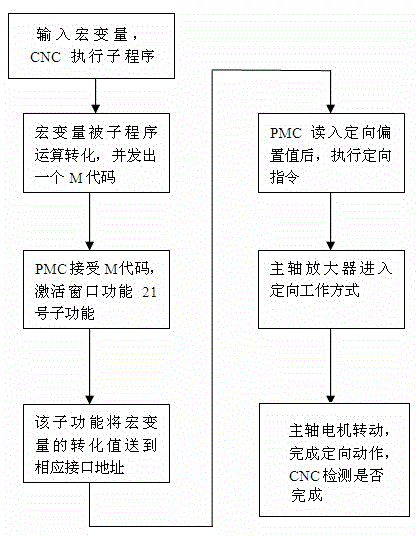
[0033] A method for multi-point orientation of a CNC machine tool spindle, comprising: a step of inputting an orientation angle in a macro variable;

[0034] In the macro program, convert the macro variable that accepts the orientation angle, add it to the spindle-defined zero-degree offset macro variable to form the final orientation off...


PUM


Abstract

The invention discloses a numerically-controlled machine tool spindle multi-point directing method. The numerically-controlled machine tool spindle multi-point directing method comprises the steps of inputting a directing angle into a macro-variable; converting the macro-variable receiving the directing angle inside a macro program, and adding the macro-variable to a customized zero offset macro-variable of a spindle to form a final directing offset and issue an M code; enabling a programmable machine tool controller to receive the M code and to activate a window twenty-first function; enabling the window twenty-first function to convey the converted value of the input parameters of the macro directing angle to the data address of the programmable machine tool controller; enable the programmable machine tool control to read in the spindle directing offset and then to execute a directing instruction. Therefore, the numerically-controlled machine tool spindle multi-point directing method can complete data conversion in the macro program through the operational function of the macro program and achieve a spindle multi-point directing function under cooperation of the window function of the programmable machine tool controller. The numerically-controlled machine tool spindle multi-point directing method is applied to the field of numerically-controlled machine tool multi-accessory automatic tool changing and numerically-controlled machine tool machining.

Description

technical field [0001] The invention relates to an orientation method, in particular to a multi-point orientation method for a spindle of a numerically controlled machine tool. Background technique [0002] In the manufacture and processing of modern CNC machine tools, as the processing objects change, more requirements are put forward for the functions of the machine tools. [0003] In the field of machine tool manufacturing, in order to expand the processing objects, different attachment heads are often attached to the machine tool. Taking the gantry-type machining center as an example, there are right-angle milling heads, horizontal milling heads, universal milling heads, etc. When the tool is changed automatically on the machine tool, the spindle end face key must stop at a certain angle, and the spindle motor is in the excitation state, but the tool change orientation angle with the attachment head is different from the tool change orientation angle without the attachm...

Claims


Application Information

Patent Timeline
Patent Type & Authority Applications(China)
IPC IPC(8): G05B19/402
CPCG05B19/402
Inventor 蒋立殷小军
Owner JIANGSU SHINRI HEAVY IND SCI & TECH
Learn More