Eureka AIR delivers breakthrough ideas for toughest innovation challenges, trusted by R&D personnel around the world.

Active soil gas collecting device and collecting method

A soil gas, active collection technology, applied in sampling devices and other directions, can solve the problems of limited collection depth, complicated operation, and difficult installation, etc., and achieve the effects of easy material, simple and convenient operation, and cost saving.

Active Publication Date: 2015-05-13
INST OF GEOGRAPHICAL SCI & NATURAL RESOURCE RES CAS
View PDF6 Cites 17 Cited by
  • Summary
  • Abstract
  • Description
  • Claims
  • Application Information

AI Technical Summary

Problems solved by technology

[0005] The purpose of the present invention is to provide a soil gas active collection device and its collection method, to solve the technical problems of the existing soil gas collection equipment and methods such as limited collection depth, complicated operation, time-consuming and labor-consuming, and difficult installation.

Method used


Image

  • Active soil gas collecting device and collecting method
  • Active soil gas collecting device and collecting method

Examples


Embodiment example 1

[0035] Implementation Case 1: The present invention has been used for soil gas collection in an ex-situ bio-pile remediation system at a site polluted by a diesel leak. According to the distribution of pollutants in the soil of the site, in a volume of 160m 3 Eight soil gas sampling points were set up in the biopile, and the sampling depths of each sampling point were 0.5m, 1.0m and 1.5m respectively. During the whole process (60 days) of remediating diesel-contaminated soil with the biological ventilation system, soil gas at different depths of soil can be collected every day to measure the content of volatile organic pollutants. The range of volatile gas concentration in the collected soil is: 0-718mg / L, to determine the distribution characteristics of volatile organic pollutants in the soil over time, and to visually display the removal of pollutants in the soil.

Embodiment example 2

[0036] Implementation Case 2: The present invention has been applied to the collection of soil gas during the heat-enhanced soil gas phase extraction process of a chlorobenzene-contaminated site in a certain chemical plant. According to the distribution characteristics of pollutants on the site and the design of the restoration system, five sampling points were designed in the site, and the sampling depth was 7m underground. Regularly collect soil gas for the determination of chlorobenzene content. The range of volatile gas concentration in the collected soil is: 40-200mg / L. According to the change of pollutant concentration in soil gas, it can effectively guide the improvement of the restoration system, and monitor the pollutants in soil gas as they are pumped out. Decrease law of extraction time and extraction rate.


PUM


Abstract

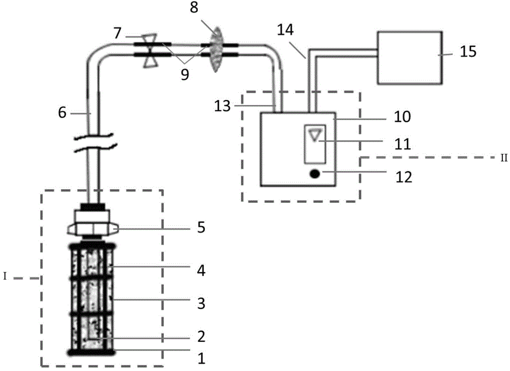
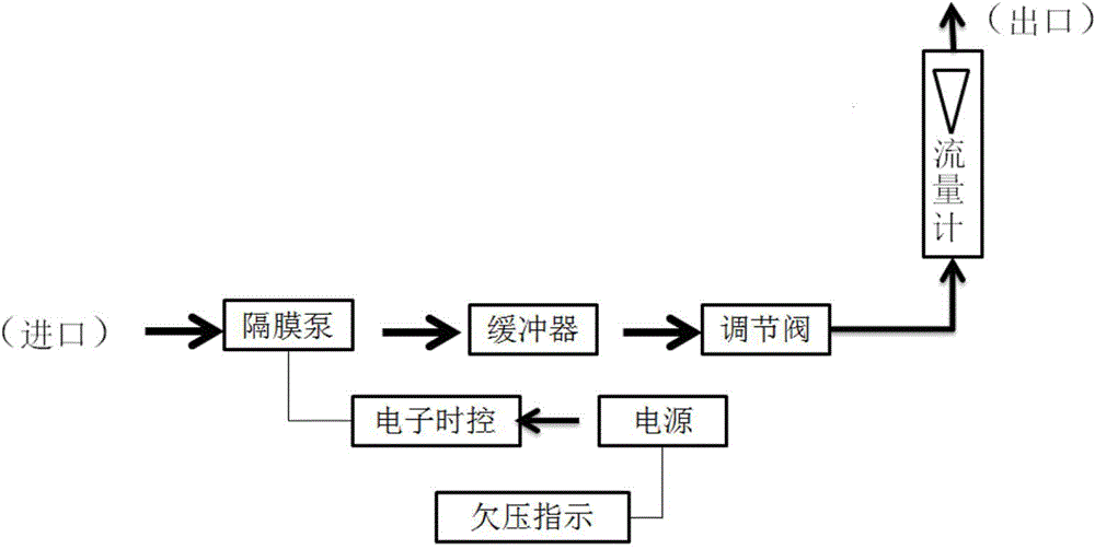
The invention discloses an active soil gas collecting device and collecting method. The active soil gas collecting device comprises a gas collecting bag, a gas sampling device, a filter, a nylon gas guiding pipe and a soil gas sucking and filtering device, wherein the gas sampling device is composed of a diaphragm pump, a regulating valve, a buffer, a flow meter, an electronic time-controlled circuit, an under-pressure indicating circuit, a power supply, a gas inlet and a gas outlet, wherein the soil gas sucking and filtering device consists of a fixed cylinder frame, a filter net, gravel, a nylon gas guiding pipe and a threaded pipe joint. When a soil gas is collected, the gas inlet pipe of the gas sampling device passes through the filter, and is connected with the nylon gas guiding pipe of the soil gas sucking and filtering device by virtue of a flexible through connection pipe, and the gas collecting bag is connected with the gas outlet pipe of the gas sampling device. The active soil gas collecting device can be used for collecting the soil gas in an existing monitoring cell, and can be distributed in soil of different depths according to a test requirement for collecting soil gases of different depth ranges, can be used for realizing long-term monitoring in the fixed-point soil, is simple in structure, high in soil gas collecting efficiency, and convenient and rapid to operate, and has a good effect.

Description

technical field [0001] The invention belongs to the field of site soil environment investigation and monitoring and soil gas collection, and in particular relates to a soil gas active collection device and a method for collecting soil gas. Background technique [0002] At present, there are not many studies on the monitoring of volatile organic pollution in soil in my country, especially the lack of strict quality control index system for the whole process of monitoring and collection of volatile organic compounds in in situ soil gas. The content of volatile organic compounds in soil is small, and the soil The gas is volatile, and the degradation of volatile organic compounds by soil microorganisms will affect the CO content in soil gas. 2 , O 2 Therefore, the monitoring process of VOC content in soil requires more effective soil gas collection devices. [0003] Accurate collection of soil gas samples is the key to the study of CO in soil gas 2 , O 2 Based on the premise ...

Claims


Application Information

Patent Timeline
Patent Type & Authority Applications(China)
IPC IPC(8): G01N1/24
Inventor 廖晓勇阎秀兰马栋
Owner INST OF GEOGRAPHICAL SCI & NATURAL RESOURCE RES CAS
Why Eureka
Eureka Blog
Learn More