
Rotational molding die and rotary molding process method

A rotational molding and process method technology, applied in the coating and other directions, can solve the problems of remaining in the product use, increase the process, danger, etc., to achieve the effect of improving production efficiency, reducing production costs, and avoiding adverse effects

Active Publication Date: 2017-02-01
KOO SHANGHAIIND CO LTD
View PDF6 Cites 0 Cited by
  • Summary
  • Abstract
  • Description
  • Claims
  • Application Information

AI Technical Summary

Problems solved by technology

[0005] The purpose of the present invention is to provide a rotary forming mold and a forming process method to solve the problem of increasing the process by using glue or solvent bonding for manual assembly when assembling and connecting the rotary formed parts with other parts in the prior art. Moreover, the use of glue or solvent bonding will leave residues in the product, causing potential hazards in use

Method used


Image

  • Rotational molding die and rotary molding process method
  • Rotational molding die and rotary molding process method
  • Rotational molding die and rotary molding process method

Examples


Embodiment Construction

[0026] Embodiments of the present invention are described below through specific examples, and those skilled in the art can easily understand other advantages and effects of the present invention from the content disclosed in this specification. The present invention can also be implemented or applied through other different specific implementation modes, and various modifications or changes can be made to the details in this specification based on different viewpoints and applications without departing from the spirit of the present invention.

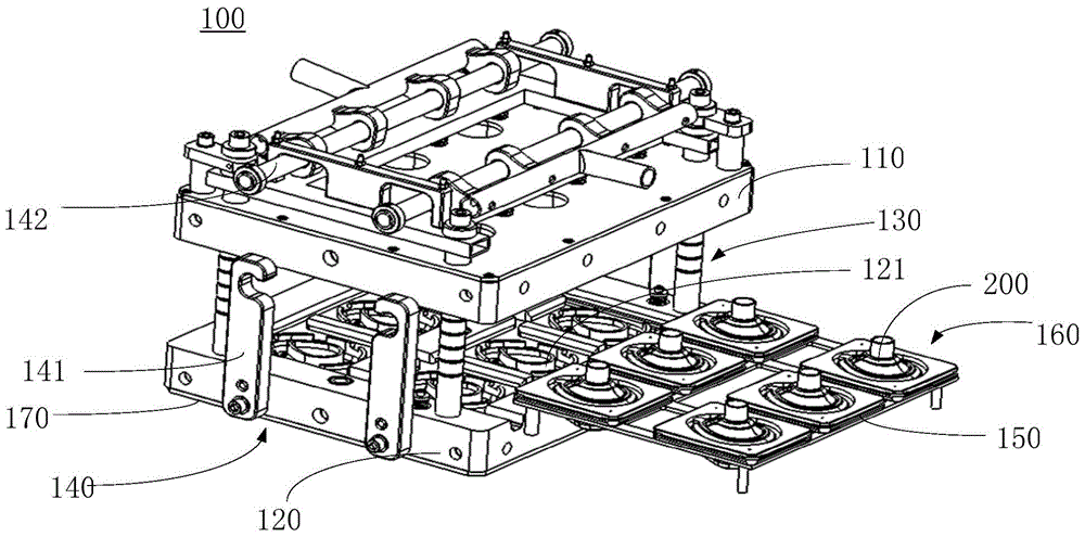
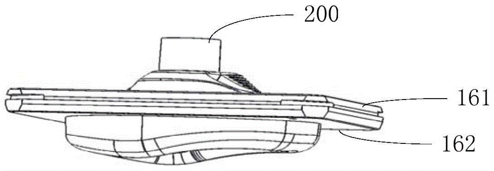
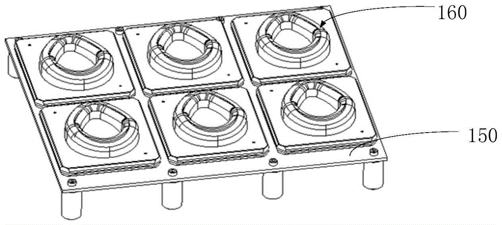
[0027] Please refer to Figure 1 to Figure 4 As shown, a rotary molding mold 100 in the embodiment of the present invention includes an upper heat-conducting template 110, a lower heat-conducting template 120, a mold guiding and closing device 130, a clamping device 140, a movable tray 150 and several cavity assemblies 160, wherein , the upper heat conduction template 110 is provided with a first part cavity, and the lower heat conduc...


PUM


Abstract

The invention discloses a rotational molding die, and a rotational molding method. According to the rotational molding die, a first part mold cavity is arranged in an upper thermal conductive template; a second part mold core is arranged in a lower thermal conductive template; each mold cavity assembly comprises a mold cover and a second part mold cavity detachably connected with the lower part of the mold cover; when a first part is inserted into a mold cover, a sealed second part die cavity is formed by the first part, the mold cover, and a corresponding second part mold cavity; the movable tray is connected with the lower thermal conductive template, and is fixedly provided with a plurality of the mold cavity assemblies, and the first parts are inserted into the mold cavity assemblies. According to the rotational molding method, rotational molding of second parts is realized, and synchronous automatic bonding of the second parts with corresponding first parts can be realized, so that subsequent bonding assembling procedures are avoided, adverse influences of binders on products are avoided, the mold cavity assemblies containing the products can be moved out of the rotational molding die for cooling at the same time, the temperature of the rotational molding die is maintained to be a rotational molding temperature, repeat temperature increasing after die cooling is avoided, molding period is shortened greatly, production cost is reduced, and production efficiency is increased.

Description

technical field [0001] The invention relates to the technical field of rotational molding, in particular to a rotational molding mold for an anesthesia breathing mask and a rotational molding process method. Background technique [0002] Rotational molding is a process for forming hollow plastic products, called rotational molding or rotational molding. Rotary molding is to add resin powder or resin solution into the mold, heat the mold and make it rotate continuously along two mutually perpendicular axes, the resin in the mold melts and is evenly coated and melted and adhered to the mold under the action of gravity and heat The inner surface is formed into the desired shape, and the workpiece is obtained after cooling. [0003] In actual product production, when the parts after rotational molding are to be assembled and connected with other parts, they are usually assembled manually by glue or solvent bonding. [0004] For example, in the manufacturing process of medical ...

Claims


Application Information

Patent Timeline
Patent Type & Authority Patents(China)
IPC IPC(8): B29C41/38B29C41/04B29C41/36
CPCB29C41/04B29C41/36B29C41/38
Inventor 黄光南万淑先王留保
Owner KOO SHANGHAIIND CO LTD
Learn More