Forward and reverse wiring tension balance control device and method for high-speed reciprocating wiring wire cutting
A reciprocating wire-feeding and electric discharge wire technology, which is applied in the direction of electrode manufacturing, manufacturing tools, electric processing equipment, etc., can solve the problem of broken wires that cannot adapt to high-speed wire-feeding, and do not consider the change of electrode wire diameter in the tension balance state of the wire-feeding system, etc. problem, achieve the effect of reducing vibration and reducing the probability of broken wire
- Summary
- Abstract
- Description
- Claims
- Application Information
AI Technical Summary
Problems solved by technology
Method used
Image
Examples
Embodiment 1
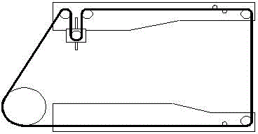
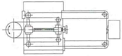
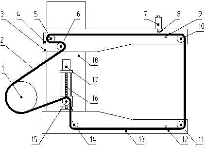
[0035] Such as image 3 , 4
[0036]A high-speed reciprocating wire electric discharge wire cutting forward and reverse wire tension balance control device, which includes a column 18 on which an upper thread arm 3 and a lower thread arm 13 are installed, and the upper thread arm 3 can move up and down on the column 18 to To adapt to the cutting requirements of workpieces of different thicknesses, the upper wire arm 3 is equipped with an upper fixed wheel 6, a tension wheel 5, a broken wire protection block 8, an upper power supply block 9 and an upper positioning guide wheel 10, and the broken wire protection block 8 is controlled by the push rod motor 7, and the tension wheel 5 is connected to the tension sensor 4; the lower positioning wheel 11, the lower power supply block 12, the lower fixed wheel 14 are installed on the lower wire arm 13, and the lower control wheel 15 is installed on the On the column 18 and controlled by the lead screw slide 16 and the stepping motor...
Embodiment 2
[0039] Such as Figure 5 shown.
[0040] A control method for balancing the forward and reverse wire tension of high-speed reciprocating wire electric discharge wire cutting, which includes the following steps:
[0041] A. According to the set electrode wire tension, use the stepper motor 17 to adjust the control wheel 15 to achieve constant tension and even wire; the specific method is to input the approximate distance between the upper and lower wire arms into the computer, and the computer analyzes and controls the driver to drive the stepper motor 17. Preliminarily adjust the position of the control wheel 15 through the screw slide 16. This step is used to preliminarily adjust the symmetry of the forward and reverse wire-traveling structure of the electrode wire. Then the required electrode wire tension is input into the computer, and the computer analyzes the data collected by the tension sensor 4 and controls the driver to drive the stepping motor 17, adjusts the contro...
Embodiment 3
[0047] Such as Figure 6 shown.
[0048] A high-speed reciprocating wire electric discharge wire cutting forward and reverse wire tension balance control device is characterized in that it includes a column 18 on which an upper wire arm 3 and a lower wire arm 13 are installed, and the upper wire arm 3 can be mounted on the column 18 Move up and down to adapt to the cutting requirements of workpieces of different thicknesses. The upper fixed wheel 6, the tension wheel 5, and the upper electric wheel 19 are installed on the upper wire arm 3, and the tension wheel 5 is connected with the tension sensor 4; the lower wire arm 13 The lower feed wheel 20 and the lower fixed wheel 14 are installed on the top, and the lower control wheel 15 is installed on the column 18 and controlled by the screw slide table 16 and the stepping motor 17. The electrode wire 2 on the wire drum 1 passes through the upper wire arm 3 The upper fixed wheel 6, the tension wheel 5 and the upper feed wheel 19...
PUM
 Abstract
Description
Claims
Application Information
 - R&D
- Intellectual Property
- Life Sciences
- Materials
- Tech Scout
- Unparalleled Data Quality
- Higher Quality Content
- 60% Fewer Hallucinations
Browse by: Latest US Patents, China's latest patents, Technical Efficacy Thesaurus, Application Domain, Technology Topic, Popular Technical Reports.
© 2025 PatSnap. All rights reserved.Legal|Privacy policy|Modern Slavery Act Transparency Statement|Sitemap|About US| Contact US: help@patsnap.com


