
A cantilever vertical lifting system

A vertical lifting and cantilever technology, applied in the field of agricultural machinery, can solve the problems of unsuitable lifting of large-mass working parts, increased hydraulic cylinder load and power consumption, poor stability, etc., to achieve good structural stability and operational safety, realize disassembly, good stability

Inactive Publication Date: 2018-04-17
GUANGXI WUFENG MACHINERY CO LTD
View PDF7 Cites 0 Cited by
  • Summary
  • Abstract
  • Description
  • Claims
  • Application Information

AI Technical Summary

Problems solved by technology

Here, the lifting device is a combination of a chain or steel wire, a sprocket or a fixed pulley and a hydraulic cylinder hanging on the gearbox. Through this structure, during the lifting process of the gearbox, since only the lower end of the hydraulic cylinder is fixed on the frame, and The upper end of the hydraulic cylinder is not only affected by the pressure, but also by the left and right thrusts. Affected by the leverage effect, there is a large torque at the fixed point with the frame, which is prone to loosening and breaking, poor structural stability, and easy to cause safety accidents; the hydraulic cylinder The displacement of the gearbox needs to be converted into the displacement of the gearbox through multiple sprockets or fixed pulleys. The higher the strength, it is not suitable for the lifting and lowering of large-mass working parts; when the hydraulic cylinder drives the gearbox to rise, it is affected by the gravity of the gearbox at the left end and the tension of the chain or wire at the right end, which increases the load and power consumption of the hydraulic cylinder. When the cylinder is lowered, because the hydraulic cylinder cannot give the transmission a downward force, the transmission only relies on its own weight for cultivation, so that the cultivation depth cannot be controlled, and it is easy to plow the soft soil too deep and the fastened soil too shallow, which is uncomfortable. It is suitable for intensive plowing and deep plowing operations; the working parts cannot rely on two guide rods to achieve structural stability, and there are deficiencies such as complex structure, poor stability, high power consumption, and difficult maintenance. It is only suitable for simple operations on small plots

Method used


Image

  • A cantilever vertical lifting system
  • A cantilever vertical lifting system

Examples


Embodiment approach

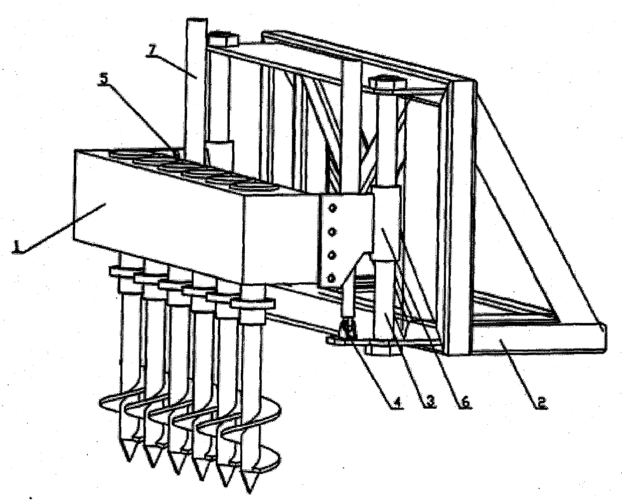
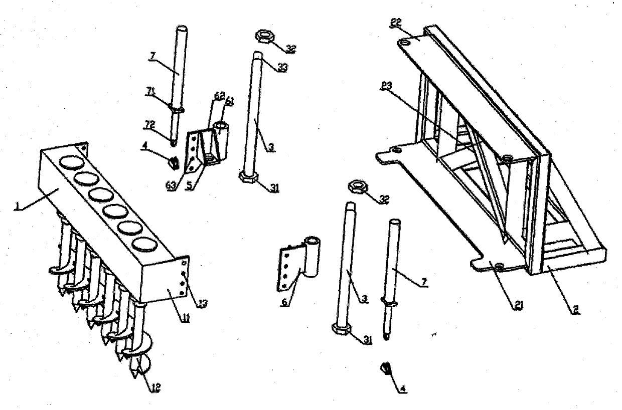
[0022] As the first embodiment of the cantilever vertical lifting system of the present invention, the frame 2 is provided with an upper plate-shaped structure 22 and a lower plate-shaped structure 21, and two guide rods 3 pass through the guide part 61 and the guide sleeve. 6 sliding connection, one end is fixedly connected with the lower plate structure 21, and the other end is fixedly connected with the upper plate structure 22. The guide rod 3 includes a bolt head 31, a threaded portion 33, and a nut 32. The guide rod passes through the through hole provided on the upper plate structure 22, the guide hole portion 61 of the guide sleeve 6, and the lower plate structure 21. The through hole, and then the nut 32 is screwed on the threaded part 33 to realize the fast connection between the guide rod 3 and the frame 2. There are two guide sleeves, and each guide sleeve 6 is provided with a connecting portion 62 and a guide hole portion 61 matched with the guide rod, and one end...


PUM


Abstract

The invention discloses a cantilever vertical lifting system, which includes a frame, a guide sleeve, a hydraulic cylinder and working parts. The working part includes an auger bit and a transmission box. , guide hole, connecting seat, the guide hole is provided with a guide hole that cooperates with the guide rod, the guide rod passes through the guide hole of the guide sleeve and is connected with the guide sleeve, the guide sleeve is fixedly connected with the transmission box of the working part, and the hydraulic pressure One end of the cylinder is hinged to the hinged seat at the lower part of the frame, the other end of the hydraulic cylinder is fixedly connected to the connecting seat of the guide sleeve through the connecting structure, each guide rod passes through the corresponding guide hole of the guide sleeve, and one end is fixed to the lower plate structure connection, the other end is fixedly connected with the upper plate-shaped structure, the guide rods are 2, connected with the guide sleeve through the guide hole, and the end points are respectively fixedly connected with the upper and lower plate-shaped structures of the frame, and the hydraulic cylinders are 2. They are respectively arranged on the guide sleeves and the brackets opposite to each other.

Description

technical field [0001] The invention relates to the field of agricultural machinery, in particular to a cantilever vertical lifting system suspended by a tractor. Background technique [0002] In the Chinese utility model patent whose authorized announcement number is CN201878501U, a kind of greenhouse deep-turning machine is disclosed, which includes a traveling device and a soil-turning device arranged at its rear end. The movable frame on the fixed frame, the lifting device controlling the up and down movement of the movable frame, the transmission device and the tensioning device are composed. The upper end is open, and the movable frame is provided with a sleeve slidingly connected with the column. The drill rod driving mechanism body of the movable frame includes a horizontal transmission shaft and a vertical drill rod shaft meshed with bevel gears, and the drill rod shafts are arranged in pairs. At the lower part of the transverse drive shaft, a drill pipe is connect...

Claims


Application Information

Patent Timeline
Patent Type & Authority Patents(China)
IPC IPC(8): A01B33/08A01B33/06
Inventor 李阳铭
Owner GUANGXI WUFENG MACHINERY CO LTD
Learn More