Continuous production device for lamp tripod

A technology for producing devices and lamp pins, which is applied in the manufacture of electrical components and electrode components, can solve the problems of difficult quality assurance and low production efficiency, and achieve the effects of saving manpower, high production efficiency and stable processing quality.

Active Publication Date: 2015-05-06
徐州博创建设发展集团有限公司
View PDF5 Cites 2 Cited by
  • Summary
  • Abstract
  • Description
  • Claims
  • Application Information

AI Technical Summary

Problems solved by technology

[0002] The existing continuous production technology of filament lamp pins all need to make U-shaped lamp pins in advance, and the production technology of U-shaped lamp pins is all manual or semi-automatic. Firstly, the production efficiency is low, and secondly, the quality is not easy to guarantee.

Method used


Image

  • Continuous production device for lamp tripod
  • Continuous production device for lamp tripod
  • Continuous production device for lamp tripod

Examples


Embodiment Construction

[0027] Now in conjunction with accompanying drawing and embodiment the present invention is described in further detail:

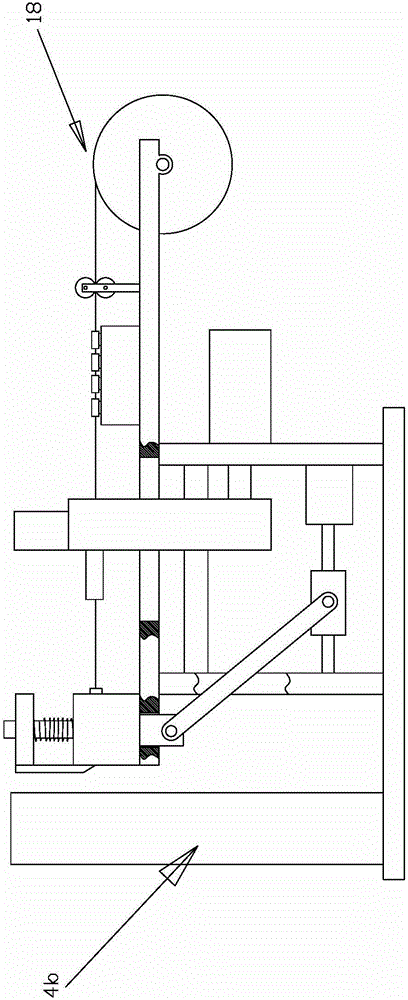
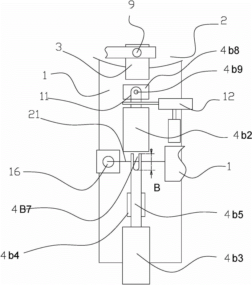
[0028] As shown in the figure, the present invention includes a frame 1, a turntable 2 driven by power arranged on the The U-shaped lamp foot forming station 4, the metal sheet welding station 5, the metal wire welding station 6, and the metal cylinder welding station 7 are arranged along the outer periphery of the turntable 2 to bend the metal wire 21 into a U-shaped metal wire 11. , blanking station 8, U-shaped lamp foot forming station 4 includes a wire feeding and cutting mechanism 18, a U-shaped lamp foot forming mechanism 4b located at the outlet end of the wire feeding and cutting mechanism 18, and a U-shaped lamp foot forming mechanism The pinching mechanism 12 at the exit of 4b, the clip opening driving mechanism 9 (as disclosed in Chinese patent application 2013102185722), the U-shaped lamp foot forming mechanism 4b includes a U-shaped metal wire...


PUM


Abstract

The invention provides a continuous production device for a lamp tripod. The device is characterized by comprising a rack, a rotating plate which is arranged on the rack and driven through power, a clamp which is arranged in the periphery of the rotating plate to clamp the lamp tripod, an U-shaped lamp tripod forming station, a metal plate welding station, a metal wire welding station, a metal barrel welding station and a blanking station, wherein all the stations are arranged on the rack and sequentially positioned along the peripheral outer sides of the rotating plate. Compared with the prior art, the device has the advantages of being fully automatic to produce the lamp tripod, labor saving, high in production efficiency, stable in processing quality, and working environmentally friendly.

Description

Technical field: [0001] The invention relates to an electric light source production device. Background technique: [0002] The existing continuous production technology of filament lamp pins all need to make U-shaped lamp pins in advance, and the production technology of U-shaped lamp pins is all manual or semi-automatic. Firstly, the production efficiency is low, and secondly, the quality is not easy to guarantee. Invention content: [0003] The purpose of the present invention is to provide a fully automatic lamp pin continuous production device that saves manpower, has high production efficiency, stable processing quality and is friendly to the working environment. [0004] The present invention is realized in this way, comprising a frame, a power-driven turntable arranged on the frame, clips arranged around the turntable for clamping lamp pins, and set on the frame along the outside of the turntable in turn. U-shaped lamp foot forming station, metal sheet weld...

Claims


Application Information

Patent Timeline
Patent Type & Authority Applications(China)
IPC IPC(8): H01K3/06H01J9/18
Inventor 李家凌
Owner 徐州博创建设发展集团有限公司
Why Eureka
Try Eureka