
Automatic production line for forming to sintering of ferrite magnetic steel and implementation method

An automatic production line, ferrite magnet technology, applied in conveyors, mechanical conveyors, transportation and packaging, etc., can solve the problems of long production cycle, low production efficiency, poor labor conditions, etc., to achieve small production area, production The effect of short cycle time and low production cost

Active Publication Date: 2015-05-06
HENGDIAN GRP DMEGC MAGNETICS CO LTD
View PDF5 Cites 3 Cited by
  • Summary
  • Abstract
  • Description
  • Claims
  • Application Information

AI Technical Summary

Problems solved by technology

[0004] 1. Low production efficiency;
[0005] 2. The product qualification rate is low and the stability is poor;
[0006] 3. The production cycle is too long, which increases the production cost;
[0007] 4. The area is too large;
[0008] 5. Poor working conditions and more manual use

Method used


Image

  • Automatic production line for forming to sintering of ferrite magnetic steel and implementation method
  • Automatic production line for forming to sintering of ferrite magnetic steel and implementation method
  • Automatic production line for forming to sintering of ferrite magnetic steel and implementation method

Examples


Embodiment 1

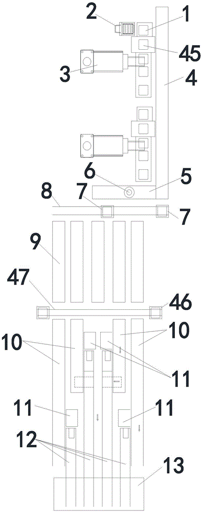
[0048] Such as Figure 1~6 As shown, an automatic production line from molding to sintering of ferrite magnets includes several empty pusher warehouses 1, empty pusher trolleys 2 are placed on the side of the empty pusher warehouses 1, and a Get embryo discharging machine and press 3, below press 3 is conveyer belt 4, image conveyer belt 5 is connected with conveyer belt 4 outlet end, image conveyer belt 5 is provided with image recognition device 6, the image recognition device in the present embodiment 6 is the product that buys on the market, and image conveyer belt 5 sides are provided with some first lift trolleys 7, and the bottom of first lift trolley 7 is provided with first slide rail 8, and first lift trolley 7 sides are provided with some A rough conveyor belt 9, a number of second lifting trolleys 46 are arranged at the outlet end of the blank conveyor belt 9, a second slide rail 47 is arranged at the bottom of the second lifting platform 46, and several kiln entra...

Embodiment 2

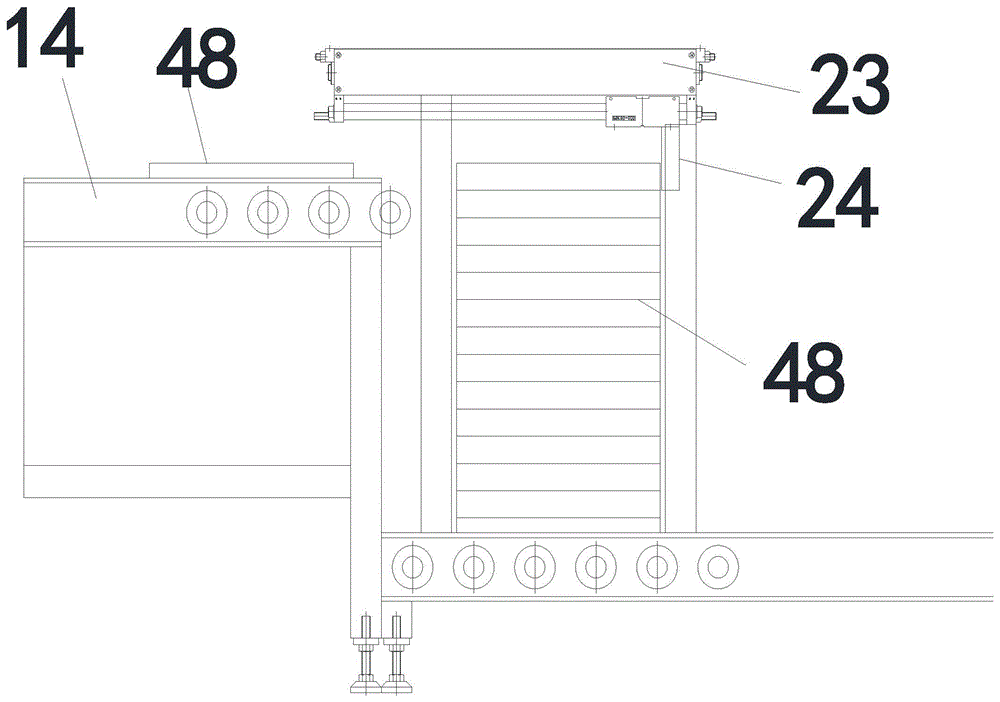
[0067] The difference between this embodiment and Embodiment 1 is that the length of the push rod 24 in this embodiment is greater than the width of the empty push plate 48, and the thickness of the push rod 24 is smaller than the thickness of the empty push plate 48. The design purpose is to use a smaller Force, the empty push pedal 48 is released correctly; The push rod 24 front is the empty push pedal waiting area 14, prepares for follow-up procedure; Caster 17 is provided with four, and caster 17 is universal wheel, convenient transfer; For forward and reverse rotation motor, realize the lifting of empty push plate 48.

[0068] The wobble plate positioning mechanism also includes an "L"-shaped clamping block, and the left clamping cylinder 29 and the right clamping cylinder 30 are respectively connected with an "L"-shaped clamping block, which can better clamp the empty push plate 48; the powder spreading device 31 includes The shell has several through holes on the bottom...


PUM


Abstract

The invention discloses an automatic production line for forming to sintering of ferrite magnetic steel. The automatic production line comprises a plurality of empty push plate warehouses, an empty push plate trolley, a blank fetching and arrangement machine, a pressing machine, a conveying belt, an image conveying belt, an image identifying device, a first lifting trolley, a first slide rail, a blank conveying belt, a second lifting trolley, a second slide rail, a kiln furnace inlet conveying belt, a kiln furnace inlet automatic plate pushing device, a kiln furnace conveying belt and a kiln furnace. The invention also discloses an implementation method for the automatic production line for forming to sintering of the ferrite magnetic steel. The automatic production line has the advantages that the structure is simple, the product quality is good, the production efficiency is high, the production area is small, the production cost is low, the production cycle is short, and the like.

Description

technical field [0001] The invention relates to the production technology of magnetic materials, in particular to an automatic production line from forming to sintering of ferrite magnetic steel and its realization method. Background technique [0002] Magnetic materials have magnetically ordered strong magnetic substances, and in a broad sense also include weak magnetic and antiferromagnetic substances that can apply their magnetic properties and magnetic effects. At present, magnetic materials are widely used in various industries. [0003] The whole production process of the magnetic material needs to go through processes such as pressing, billet making, and sintering. However, in the prior art, the processes of pressing, transferring, and sintering the blank require manual operations. Such technology will have the following technical problems: [0004] 1. Low production efficiency; [0005] 2. The product qualification rate is low and the stability is poor; [0006] ...

Claims


Application Information

Patent Timeline
Patent Type & Authority Applications(China)
IPC IPC(8): B65G37/00
Inventor 牛利博林百煌严威飞王斌杨海涛方秀平
Owner HENGDIAN GRP DMEGC MAGNETICS CO LTD
Learn More