
Hole drilling machine special for ranks machine

A technology of boring machine and column machine, which is applied in the direction of boring/drilling, drilling/drilling equipment, metal processing equipment, etc., which can solve the problems of rapid upgrade of unfavorable equipment, increase of production cost, and long transformation period, etc., to achieve Avoid dismantling of foreign transport processing, reduce workload, save the effect of dismantling and installation work

Inactive Publication Date: 2015-05-06
SHANDONG PHARMA GLASS
View PDF6 Cites 0 Cited by
  • Summary
  • Abstract
  • Description
  • Claims
  • Application Information

AI Technical Summary

Problems solved by technology

[0003] The old queue machines have been better utilized after transformation, creating greater profits for the enterprise again, but a problem has been exposed in the actual production and transformation. First, if it is transformed under normal production conditions, it will cause expensive Second, if the workshop is overhauled and shut down to carry out renovation, the overhaul cycle of each workshop will generally take about four years. According to this progress, the renovation period is too long, which is not conducive to the maintenance of all equipment. Rapid upgrade. In addition, after dismantling the various pipelines and gas circuits, a large part cannot be used again, causing waste and increasing production costs.

Method used


Image

  • Hole drilling machine special for ranks machine
  • Hole drilling machine special for ranks machine
  • Hole drilling machine special for ranks machine

Examples


Embodiment Construction

[0024] Embodiments of the present invention are further described below in conjunction with accompanying drawings:

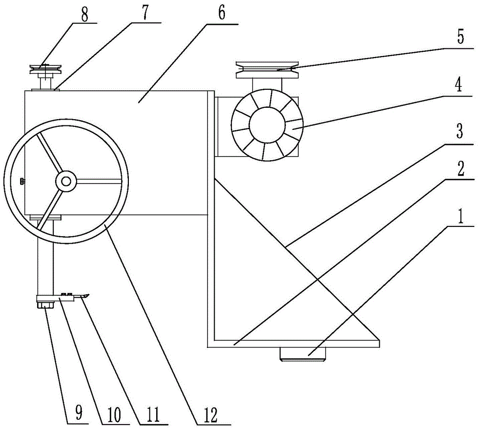
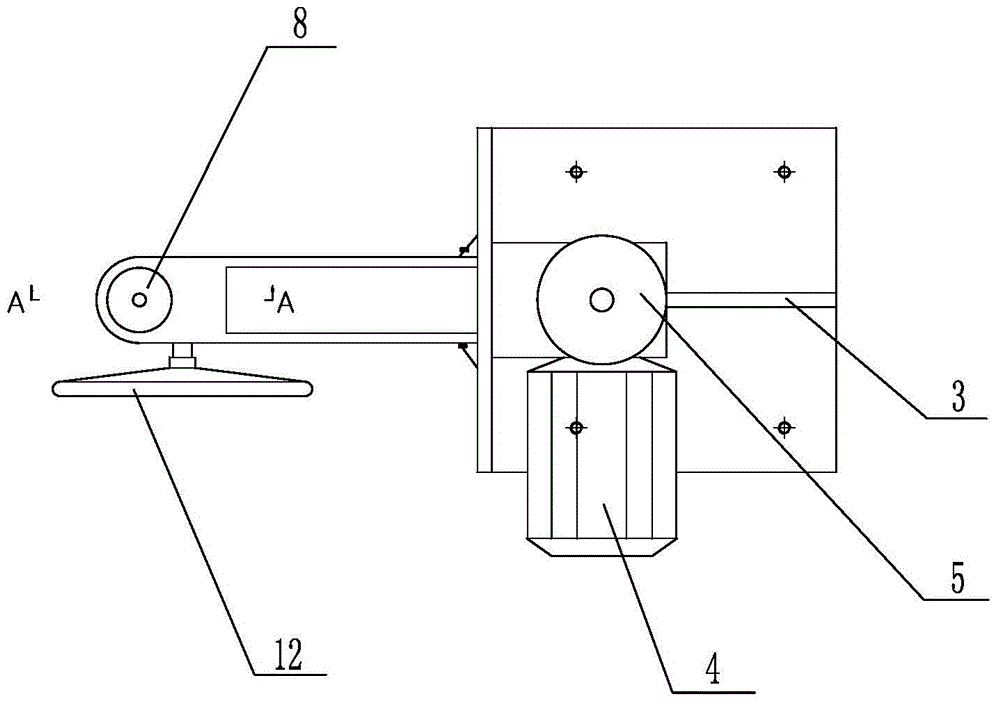
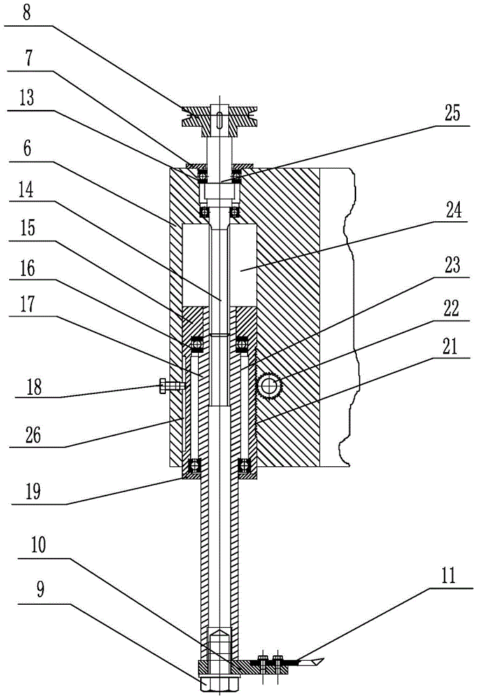
[0025] like Figure 1-Figure 3 As shown, the special boring machine for rank machine of the present invention comprises an L-shaped bracket 2, on the L-shaped bracket 2, the reinforcing rib 3 is fixed by bolts, the lower end of the L-shaped bracket 2 is provided with a positioning end 1, and the upper part of the L-shaped bracket 2 is a The side is fixedly connected to the deceleration motor 4 by four bolts, the deceleration motor 4 is connected to the driving pulley 5, and the corresponding deceleration motor 4 is installed on the other side of the L-shaped bracket 2 with a fixed housing 6, and the part of the fixed housing 6 close to the bracket 2 is a hollow structure , the hollow structure accounts for two-thirds of the entire fixed housing 6, the front end of the fixed housing 6 is equipped with a spline shaft 14, the top of the spline shaft 14 is connected...


PUM


Abstract

The invention relates to a hole drilling machine special for a ranks machine, belonging to the technical field of mechanical equipment. The lower end of a bracket is provided with a positioning end socket, and the upper part of the bracket is provided with a speed-reducing motor and a fixing shell; the speed-reducing motor is connected with a driving pulley; the front end of the fixing shell is provided with a spline shaft; the top part of the spline shaft is connected with a driven pulley through a transmission component; a first bearing is arranged on the connection part of the spline shaft and the transmission component; the outer side of the spline shaft is provided with a spline housing in a sleeving way; the spline housing is provided with a sleeve shaft cavity; the outer side of the spline housing is provided with a bulge and is provided with a gear sleeve in the sleeving way; a second bearing is arranged among two ends of the bulge and the gear sleeve; the gear sleeve is arranged inside a cavity of the fixing housing; one side of the gear sleeve is provided with a groove; the fixing housing is provided with a limit bolt by coordinating with the groove; the other side of the gear sleeve is provided with teeth meshed with a gear; the gear is connected with a hand wheel; the bottom part of the spline shaft is provided with a tool apron and a boring cutter. According to the invention, the structure is simple; the device does not need to be dismantled and installed; the ranks machine can be transformed at any time; the transformed period is shortened; the production cost is reduced; the economic benefit is improved.

Description

technical field [0001] The invention relates to a boring machine, in particular to a special boring machine for row and column machines, which belongs to the technical field of mechanical equipment. Background technique [0002] At present, in order to improve the performance of the rank machine after a period of use, it is necessary to modify the various mechanisms of the rank machine to varying degrees. After the transformation, the operating performance of the rank machine will be significantly improved, and the operation stability of the equipment, And the quality of products has been significantly improved. However, when transforming the rank machine, all the mechanisms need to be dismantled first, and then the frame of the rank machine is transported to a designated processing unit, and processed by a large boring machine or a machining center. The most important part is to enlarge the original installation hole After the processing is completed, it will be transporte...

Claims


Application Information

Patent Timeline
Patent Type & Authority Applications(China)
IPC IPC(8): B23B41/00
CPCB23B41/00
Inventor 张军张兴柱张乐军弋康锋
Owner SHANDONG PHARMA GLASS
Learn More