
Control circuit of power conversion circuit and relevant capacitor charging circuit

A power conversion circuit and control circuit technology, which is applied to control/regulation systems, output power conversion devices, electrical components, etc., can solve the problems of the power conversion circuit being unable to operate normally, consumption, and insufficient charge of the bootstrap capacitor. The effect of saving circuit area, simplifying architecture, reducing component complexity and cost

Inactive Publication Date: 2015-04-29
RICHTEK TECH
View PDF9 Cites 4 Cited by
  • Summary
  • Abstract
  • Description
  • Claims
  • Application Information

AI Technical Summary

Problems solved by technology

During this phase, the charge stored in the bootstrap capacitor will be gradually consumed by other components in the power conversion circuit
Therefore, when the power conversion circuit leaves the power-saving operation mode and enters the normal operation mode, the high-side switch cannot be turned on smoothly due to the insufficient charge of the bootstrap capacitor, resulting in the failure of the power conversion circuit to operate normally.

Method used


Image

  • Control circuit of power conversion circuit and relevant capacitor charging circuit
  • Control circuit of power conversion circuit and relevant capacitor charging circuit
  • Control circuit of power conversion circuit and relevant capacitor charging circuit

Examples


Embodiment Construction

[0037] Embodiments of the present invention will be described below in conjunction with related drawings. In the drawings, the same reference numerals represent the same or similar elements or method flows.

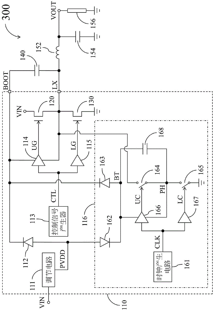
[0038] figure 1 It is a simplified functional block diagram of the power conversion circuit 100 according to an embodiment of the present invention. The power conversion circuit 100 includes a control circuit 110 , a high-side switch 120 , a low-side switch 130 , a bootstrap capacitor 140 , an inductor 152 , an output capacitor 154 , and a load 156 . The control circuit 110 is coupled to the upper bridge switch 120 and the lower bridge switch 130 and configured to control the operation of the upper bridge switch 120 and the lower bridge switch 130 . The high-bridge switch 120 is coupled between the input terminal of the power conversion circuit 100 and the first node LX. The low bridge switch 130 is coupled between the first node LX and a fixed potential terminal (suc...


PUM


Abstract

The invention discloses a control circuit of a power conversion circuit and a relevant capacitor charging circuit. The capacitor charging circuit used for the power conversion circuit and provided by the embodiment of the invention comprises a clock generation circuit for generating a clock signal, a second diode coupled between an adjusting circuit and a third node, a third diode coupled between the third node and a second node, a first switch coupled between a first node and a fourth node, a second switch coupled between the fourth node and a fixed potential end, a first drive circuit used for controlling the first switch according to the clock signal, a second drive circuit used for controlling the second switch according to the clock signal, and a charging capacitor coupled between the third node and the fourth node. When the clock signal is positioned at a first potential, the first drive circuit is used for turning off the first switch and the second drive circuit is used for turning on the second switch; when the clock signal is positioned at a second potential, the first drive circuit is used for turning on the first switch and the second drive circuit is used for turning off the second switch, thereby ensuring that sufficient electric charges of a bootstrap capacitor can be maintained.

Description

technical field [0001] The present invention relates to a power converter, in particular to a control circuit capable of ensuring normal operation of a power switch of the power converter and a related capacitor charging circuit. Background technique [0002] In some power conversion circuits that use NMOS transistors to implement power switches, if it is necessary to operate the upper bridge switch at a higher load ratio (for example, 100% load ratio), it is usually necessary to add an automatic switch in the power conversion circuit. Only a bootstrap capacitor and a corresponding capacitor charging circuit can provide the extra charge required for the operation of the upper bridge switch. The more complex the structure of the capacitor charging circuit, the larger the circuit area required to be occupied. [0003] In addition, in order to improve energy efficiency, supporting power-saving operation mode has gradually become a design trend of power conversion circuits. Wh...

Claims


Application Information

Patent Timeline
IPC IPC(8): H02M1/00H02M3/155
CPCH02M1/088H02M3/155
Inventor 陈安东汪若瑜
Owner RICHTEK TECH
Learn More