
A Coordinated Control Method for Power Balance of Solar Energy Storage High Penetration DC Microgrid

A technology of DC micro-grid and power balance, which is applied in the direction of DC network circuit devices, DC power supply parallel operation, photovoltaic power generation, etc. It can solve the problems of voltage control static difference, achieve the effect of eliminating bus voltage static difference and realizing capacity balance

Active Publication Date: 2016-08-17
ZHEJIANG UNIV +1
View PDF7 Cites 0 Cited by
  • Summary
  • Abstract
  • Description
  • Claims
  • Application Information

AI Technical Summary

Problems solved by technology

In addition, based on the V / P droop characteristic, the droop coefficient is designed as a function of the SoC. Although the above droop control finally realizes voltage control and current distribution, due to the droop characteristic, the voltage control always has a static error. It is very necessary to have a method that can not only ensure the control of voltage without static difference but also realize the reasonable distribution of current

Method used


Image

  • A Coordinated Control Method for Power Balance of Solar Energy Storage High Penetration DC Microgrid
  • A Coordinated Control Method for Power Balance of Solar Energy Storage High Penetration DC Microgrid
  • A Coordinated Control Method for Power Balance of Solar Energy Storage High Penetration DC Microgrid

Examples


Embodiment 1

[0078] This embodiment analyzes U dc The deviation direction and deviation time, and realize U dc Under different deviation directions and deviation times, the system controls it through flexible switching between different working modes to stabilize it at U N The safe range (U N -U S ≤ U dc ≤ U N + U S )Inside.

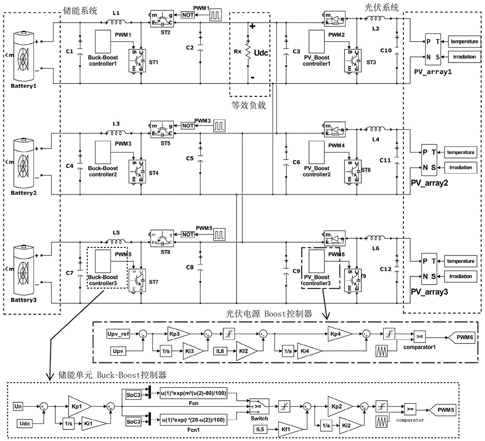
[0079] In Example 1, the DC microgrid includes two energy storage units and three photovoltaic power sources (maximum power 2700kW); please refer to the photovoltaic system and energy storage system controller figure 2 .

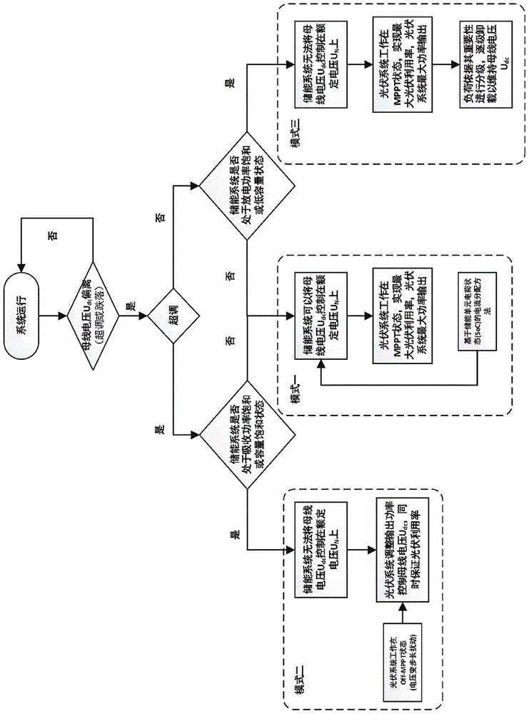
[0080] see figure 1 , the specific implementation strategy is:

[0081] 1. Each node of the DC microgrid system obtains local-based control information, in which each energy storage unit obtains the state of charge, operating voltage, and operating current locally; each photovoltaic power source obtains output voltage and output current locally; at the same time, each node shares DC bus voltage U dc ;

[0082] 2. Occurrence of U due to...

Embodiment 2

[0118] In this embodiment, the energy storage system can control U dc , that is, the system always works in mode 1, fully considers the state of charge of each energy storage unit in the energy storage system, reasonably distributes the current of the energy storage units in the energy storage system, adjusts the output power of each energy storage unit, and ensures the bus voltage U dc No static difference tracking rated voltage U N At the same time, the capacity gap between energy storage units is gradually narrowed, and the capacity balance between each energy storage unit is realized.

[0119] Embodiment 2 includes two energy storage units, a photovoltaic power supply, initial SoC (1)=60%, and initial SoC (2) is respectively 55%, 50%, 45% for comparison; the photovoltaic system works under the MPPT state, The maximum output power is 900kW; please refer to the photovoltaic system and energy storage system controller figure 2 .

[0120] 1. The initial charge of energy st...

Embodiment 3

[0131] In this embodiment, the energy storage system can control U dc , that is, the system always works in mode 1. In this mode, the impact of the withdrawal and connection of the energy storage unit on the energy storage system is mainly described. The system can ensure the stability of the bus voltage and achieve the capacity balance between the energy storage units. Realize high-penetration optical storage access.

[0132] Embodiment 3 includes three energy storage units, a photovoltaic power supply, and the initial charge of the three energy storage units are 60%, 55%, and 50% respectively; the photovoltaic system works in the MPPT state, and the maximum output power is 1800kW; the photovoltaic system and energy storage system controller, please refer to figure 2 .

[0133] Such as Figure 12 and Figure 13 , because the initial charge of the energy storage unit 3 (50%) is smaller than the other two (60%, 55%), the output power is very low, and the decrease of the ch...


PUM


Abstract

The invention discloses a power-balance coordination control method for light storage high-permeability direct-current micro-networks. Under a direct-current micro-network environment, the system control is realized by the local control of nodes, and the power-balance coordination control method is suitable for high-permeability light storage access. When a load accesses / exists, the output power of a photovoltaic system, the input and output power and the capacity of an energy storage system change, the photovoltaic system and the energy storage system control a direct-current bus voltage in a coordination manner so as to keep the power of the load, the photovoltaic system and the energy storage system balanced, a plurality of energy storage units in the systems are controlled in a coordination manner under the precondition that the non static difference of the direct-current bus voltage is guaranteed to be stable at a rated value, the capacity balance of the energy storage units of the energy storage system is sufficiently considered, and the reasonable distribution of electric current is realized; besides, the photovoltaic system is flexibly switched to work under MPPT and Off-MPPT states, and the use ratio of the photovoltaic system and the stability of a direct-current micro-network system under the two states can be guaranteed.

Description

technical field [0001] The invention relates to the field of microgrid operation control and energy dispatching, in particular to a power balance coordinated control method suitable for high-permeability optical-storage access under a DC microgrid. Background technique [0002] In recent years, in order to reduce the emission of greenhouse gases and reduce the consumption of fossil fuels, in order to cope with the increasingly severe environmental pollution and energy crisis, the penetration rate of many renewable clean energy such as wind energy, solar energy, tidal energy, etc. in the power grid has gradually increased. . However, due to the intermittent and distributed characteristics of some renewable energy sources, directly connecting them to the grid will affect the power quality of the grid. The main way to solve this problem. Compared with AC microgrids, there is no need to consider power quality issues such as reactive power compensation, frequency synchronizatio...

Claims


Application Information

Patent Timeline
Patent Type & Authority Patents(China)
IPC IPC(8): H02J1/10H02J7/35
CPCH02J1/102H02J1/106H02J7/35Y02E10/56
Inventor 杨强曾红梅赵海麟刘德才颜文俊
Owner ZHEJIANG UNIV
Learn More