
Voltage stabilizing circuit and method thereof

A voltage stabilizing circuit and voltage technology, applied in the direction of adjusting electrical variables, control/regulation systems, instruments, etc., can solve the problems of slow recovery to normal working state, large working current, increased power loss, etc.

Active Publication Date: 2016-04-06
HOLTEK SEMICON
View PDF6 Cites 0 Cited by
  • Summary
  • Abstract
  • Description
  • Claims
  • Application Information

AI Technical Summary

Problems solved by technology

[0004] There is still at least one problem in the current overcurrent protection circuit applied to the voltage regulator, for example: the bias voltage of the voltage regulator under normal working conditions is affected due to the continuity detection mechanism, and the overcurrent and short circuit current cannot be simultaneously present. Protection ability, relatively increased power loss, relatively large operating current, and relatively slow return to normal working conditions, etc.

Method used


Image

  • Voltage stabilizing circuit and method thereof
  • Voltage stabilizing circuit and method thereof
  • Voltage stabilizing circuit and method thereof

Examples


Embodiment Construction

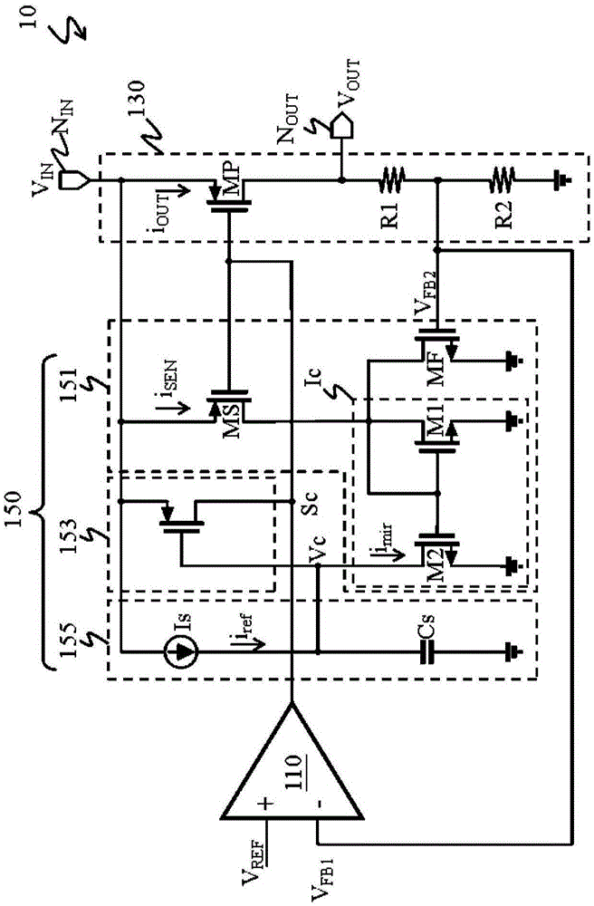
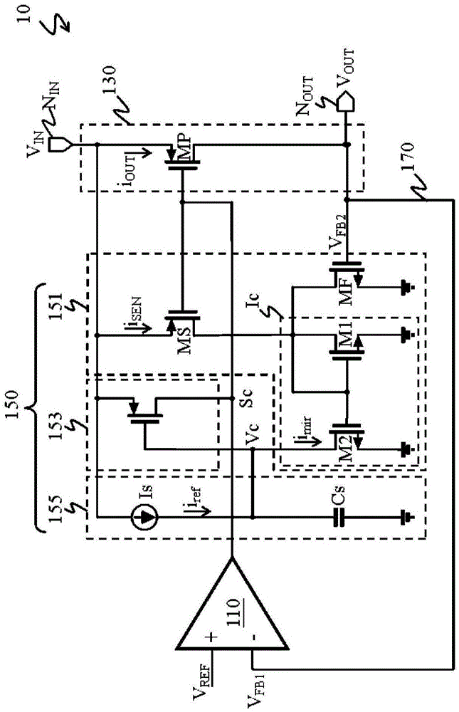
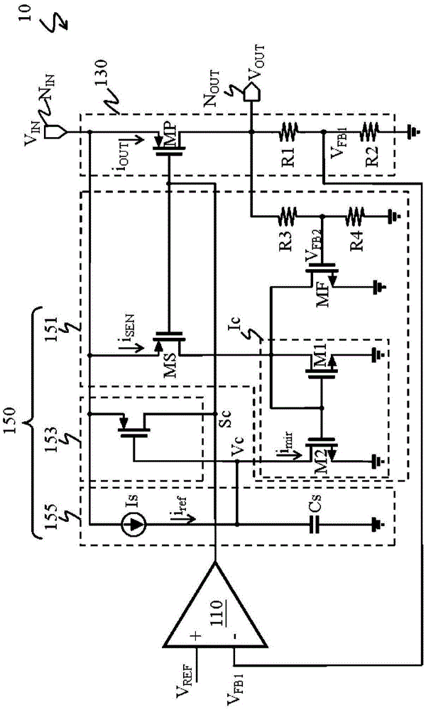
[0049] refer to figure 1 , The voltage stabilizing circuit 10 includes: an error amplifier 110 , an output circuit 130 and an overcurrent protection circuit 150 .

[0050] The overcurrent protection circuit 150 includes a current sensing circuit 151 , a protection switch 153 and a judgment circuit 155 . The current sensing circuit 151 includes a sensing element MS and a variable current source Ic.

[0051] The output terminal of the error amplifier 110 is electrically connected to the output circuit 130 and the control terminal of the sensing element MS. The input end of the output circuit 130 is electrically connected to the power contact N IN , and the output terminal of the output circuit 130 is electrically connected to the load contact N OUT .

[0052] Here, the output circuit 130 includes a power element MP. The power element MP has a first terminal, a second terminal and a control terminal. The control terminal of the power element MP and the control terminal of t...


PUM


Abstract

The invention discloses a voltage regulator circuit and a method thereof. A voltage regulator circuit includes an error amplifier, an output circuit, a current sensing circuit, a protection switch and a decision circuit. The error amplifier generates a control signal according to a reference voltage and a feedback voltage. The output circuit has a power element, and the power element converts a supply voltage to an output voltage according to the control signal. The feedback voltage is related to the output voltage. The current sensing circuit generates a current sensing signal corresponding to an output current flowing through the power element. The decision circuit controls the protection switch to clamp the control signal according to the current sensing signal and a current reference signal.

Description

technical field [0001] The invention relates to the technology of providing stable voltage, in particular to a voltage stabilizing circuit and its method. Background technique [0002] A voltage regulator is generally disposed between a power supply and a load circuit to provide a stable output voltage to the load circuit based on the supply voltage. The voltage regulator uses an error amplifier (erroramplifier) ​​to control the conduction state of the power element according to the comparison result between the first feedback voltage and the reference voltage, and converts the supply voltage into an output voltage through the power element. When the load current changes, the voltage regulator uses a feedback mechanism to stabilize the output voltage. [0003] Voltage regulators have the advantages of low noise and high precision, so they are widely used in power management. But also because of the wide range of applications, the voltage regulator must have many protection...

Claims


Application Information

Patent Timeline
Patent Type & Authority Patents(China)
IPC IPC(8): G05F1/56
Inventor 陈逸先
Owner HOLTEK SEMICON
Learn More