A small environmental control device for airborne stabilization

A stable aiming and environmental control technology, which is applied in the direction of using electric means for temperature control, auxiliary controllers with auxiliary heating devices, etc., can solve the problems of reducing heat generation, the temperature control effect is difficult to achieve the expected effect, etc., and achieves heat dissipation efficiency. Improvement, good thermal conductivity and heat dissipation effect, strong controllable effect

Active Publication Date: 2016-11-23
西安应用光学研究所
View PDF2 Cites 0 Cited by
  • Summary
  • Abstract
  • Description
  • Claims
  • Application Information

AI Technical Summary

Problems solved by technology

[0003] In addition, the biggest feature of the internal heat source of the photoelectric stabilization turret is that it can move relative to the sealed spherical shell, and it cannot be directly connected to the outer spherical shell with a high-efficiency heat-conducting medium. Therefore, the current domestic airborne photoelectric stabilization system often uses limited The working time of the sensor and the installation of a fan can be used to adjust the temperature. The former can reduce the total calorific value in the shell, and the latter can increase the heat transfer rate of the heat transfer medium-nitrogen. The temperature control effect has become more and more difficult to achieve the expected effect, so there is an urgent need for a miniaturized and efficient environmental control system that adapts to the special working characteristics of the photoelectric stabilized aiming turret

Method used


Image

  • A small environmental control device for airborne stabilization
  • A small environmental control device for airborne stabilization
  • A small environmental control device for airborne stabilization

Examples


Embodiment Construction

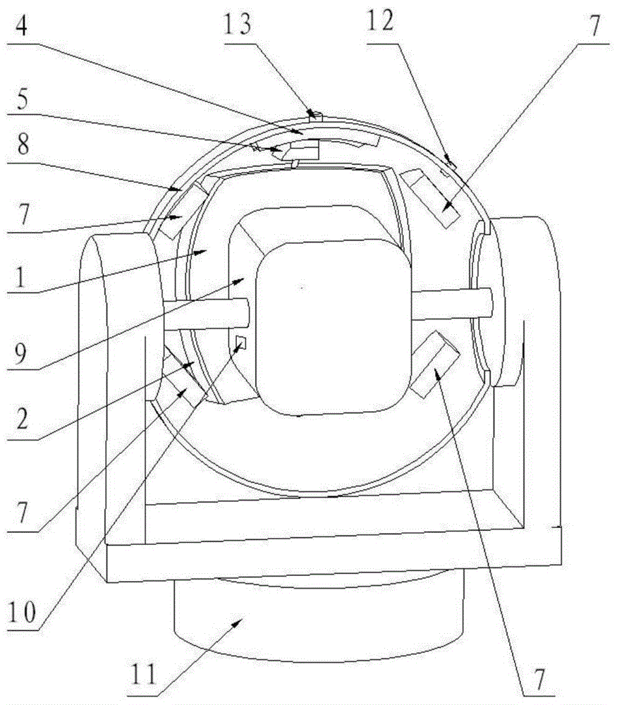
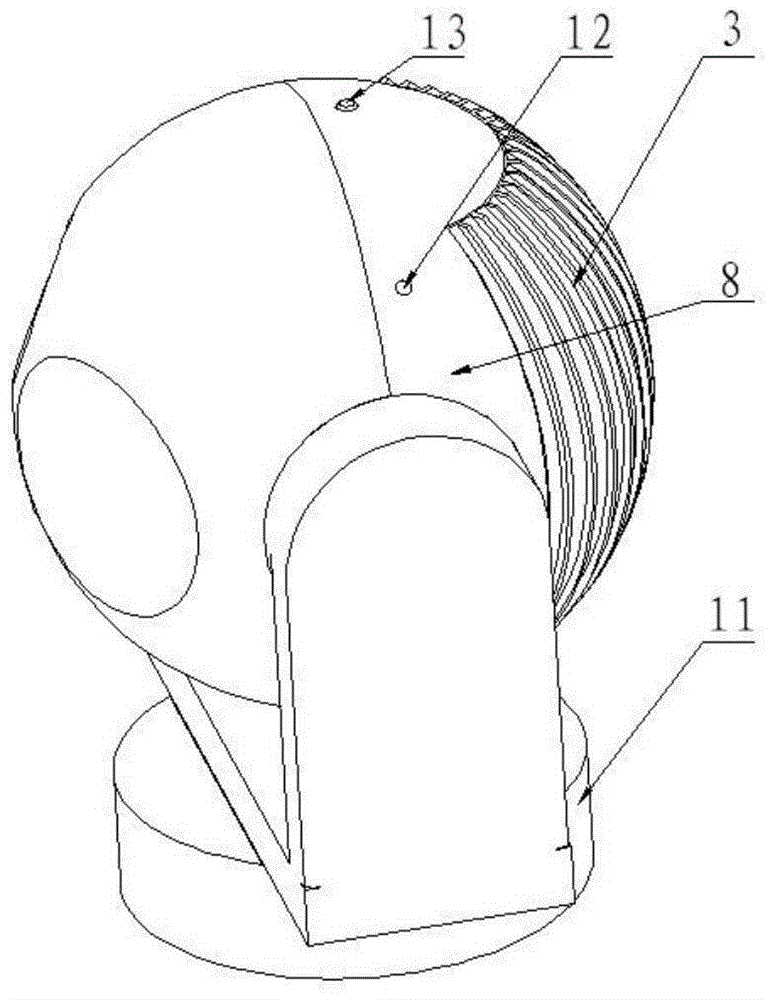
[0033] The specific implementation modes and examples of the present invention will be described in detail below in conjunction with the accompanying drawings.

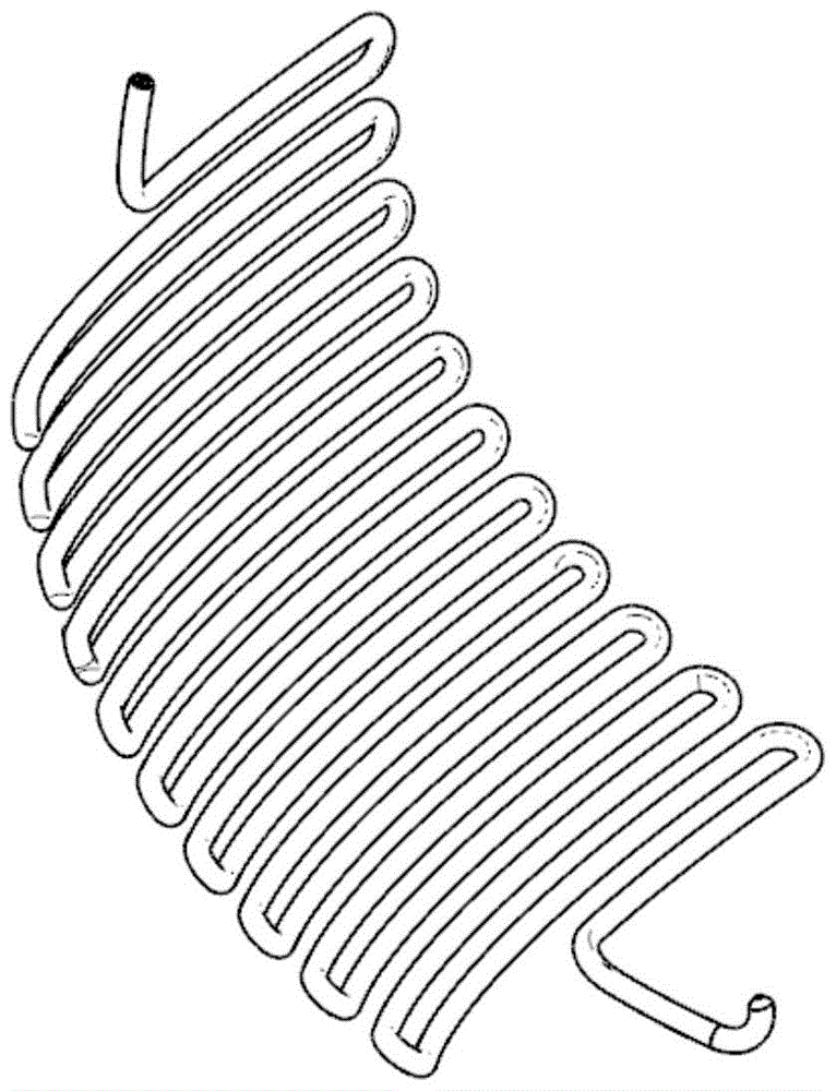
[0034] The airborne small-scale environmental control device for stabilizing aiming provided by the present invention includes components such as thermoelectric cooling module, fan, liquid cooling module, fin-shaped heat sink and temperature control system, wherein the fin-shaped heat sink is installed outside the sealed spherical shell of the stabilized aiming turret , used to supplement and enhance the external heat dissipation efficiency of the photoelectric turret, and the rest of the components are installed in the sealed spherical shell to directly provide high-efficiency cooling for the heat source in the shell. The invention can effectively improve the internal temperature environment of the aiming turret while maintaining the airtight characteristic of the spherical shell.

[0035]The thermoelectric refrigera...


PUM


Abstract

The invention provides a small ring control device for onboard alignment stabilizing. The small ring control device mainly comprises a thermoelectric refrigeration module, a fan, a liquid refrigeration module, fin-type radiating fins and a temperature control system. The thermoelectric refrigeration module is tightly attached to a sealed spherical shell. A refrigeration face surrounds a light-emitting source inside the shell. Waste heat of the light-emitting source is transmitted to the fin-type radiating fins outside the shell through a radiating box and a metal shell body, and finally radiation is accelerated through strong gas flow generated by a carrier; a plurality of S-shaped gasification pipelines are arranged inside the radiating box, a light-emitting face of the thermoelectric refrigeration module is evenly cooled when low-temperature liquid flows, and the environment inside the shell can be cooled through low-temperature gas generated at the tail end; the fan can enhance the thermal conductivity of a heat exchange region; the temperature control system can automatically adjust the power and the working mode of a secondary refrigerator according to the actual temperature of the heat source inside the shell. Compared with traditional fan ring control, the small ring control device has the advantages of being wide in temperature control range and high in initiative. Compared with a mechanical ring control system, the small ring control device has the advantages of being small in size, simple in structure and high in reliability.

Description

technical field [0001] The invention belongs to the field of internal environment control of an airborne photoelectric stabilization turret, in particular to a small-sized environment control device for airborne stabilization. Background technique [0002] At present, the airborne photoelectric stabilized aiming turret is widely used in various occasions such as search and rescue, forest fire prevention, and remote observation. A series of photoelectric sensors such as sights and sights, infrared thermal imaging cameras, laser photometers, trackers, etc., and signal processing units such as computer boards and servo control boards. In practice, in order to ensure that the above-mentioned devices are protected from external factors such as moisture, sand, rain and snow, they are often packaged in a sealed case and filled with high-purity dry nitrogen for isolation protection. Moreover, in order to ensure that the aircraft can carry more payload under the existing maneuverabi...

Claims


Application Information

Patent Timeline
Patent Type & Authority Patents(China)
IPC IPC(8): G05D23/30
Inventor 朱镭纪明孔龙阳
Owner 西安应用光学研究所
Why Eureka
Try Eureka