Equipment monitoring and diagnosis device
A diagnostic device and equipment technology, applied in the direction of electrical testing/monitoring, testing/monitoring control systems, instruments, etc., can solve problems such as equipment degradation and other information omissions
- Summary
- Abstract
- Description
- Claims
- Application Information
AI Technical Summary
Problems solved by technology
Method used
Image
Examples
Embodiment approach 1
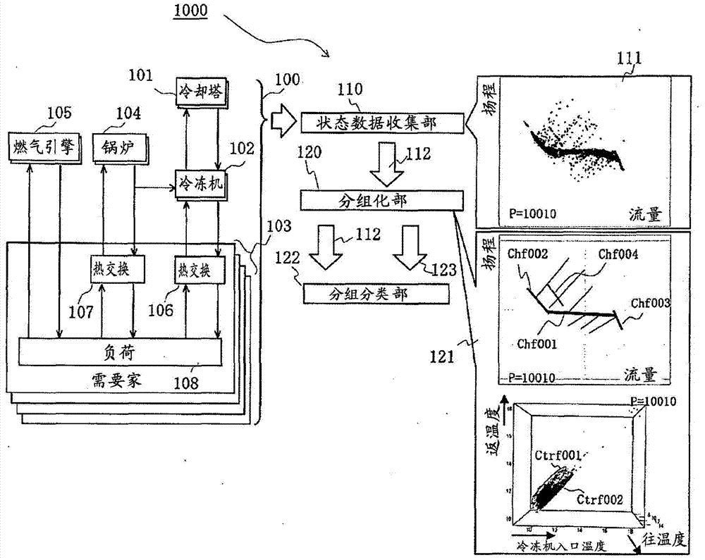
[0029] figure 1 It is a block diagram of Embodiment 1 of the monitoring and diagnosing apparatus of the equipment of this invention.
[0030] The equipment group 100 to be monitored includes heat source equipment such as a cooling tower 101 , a refrigerator 102 , a boiler 104 , and a gas engine 105 , and a customer 103 . All of them are composed of one or more devices and needs of the same type. In addition, each customer 103 has heat exchangers 106 and 107 that receive heat from a heat source, and a load 108 . In addition, the heat exchangers 106 and 107 cannot necessarily be said to be essential equipment. In addition, although not shown here, a liquid delivery pump for driving a heating agent such as water or hot water, a driving device for this, a valve, and the like are also targeted.
[0031] The monitoring and diagnosing device 1000 includes: a state data collection unit 110 for each function such as liquid feeding and heat supply, and collects process quantities fro...
Embodiment approach 2
[0037] figure 2 It is a configuration diagram of Embodiment 2 of the device monitoring and diagnosing device of the present invention, and is a monitoring and diagnosing device 2000 that applies (1) the method of using the efficiency of the entire device when judging the validity of the operating state.
[0038] In the case of using the operating efficiency of the equipment, the efficiency of the entire equipment to be evaluated is calculated based on the efficiency evaluation formula registered in the efficiency evaluation formula storage unit 142 and the data collected by the data collection unit 110 in advance, and the group classification unit 122 In this process, the result (group classification result data 124 ) obtained for the probability that the process state at this time belongs to each group is used, and the group efficiency learning unit 140 that associates each group with efficiency is used. In addition, the efficiency evaluation expression recorded in the effic...
Embodiment approach 3
[0041] image 3 It is a configuration diagram of Embodiment 3 of the monitoring and diagnosing device for equipment according to the present invention, and is a monitoring and diagnosing device 3000 that applies (2) the method of using operating conditions determined in advance at the time of design, etc., when judging the validity of the operating state .
[0042] The operating conditions assumed at the design time point correspond to the design concept such as "the liquid delivery function is based on the constant pressure control of the pump". In order to deal with them in the monitoring and diagnosing device 3000, use: assume the running state storage unit 150 to define such a state with a simple definition; Feature grouping extraction result data 123), evaluate the degree to which the grouping corresponds to the assumed operating state; and the assumed state grouping relationship development part 152, evaluate the relationship between the assumed operating state defined ab...
PUM
 Abstract
Description
Claims
Application Information
 - R&D
- Intellectual Property
- Life Sciences
- Materials
- Tech Scout
- Unparalleled Data Quality
- Higher Quality Content
- 60% Fewer Hallucinations
Browse by: Latest US Patents, China's latest patents, Technical Efficacy Thesaurus, Application Domain, Technology Topic, Popular Technical Reports.
© 2025 PatSnap. All rights reserved.Legal|Privacy policy|Modern Slavery Act Transparency Statement|Sitemap|About US| Contact US: help@patsnap.com


