Optical fiber conduction device in chemical light emission measuring chamber

A technology of chemiluminescence and conduction devices, which is applied in the field of medical devices, can solve the problems of not considering the optical path difference between the luminescent object and the photomultiplier tube, and the deviation of the measurement results, so as to reduce the measurement error and achieve the effect of accurate measurement results

Inactive Publication Date: 2015-04-29
SUZHOU HYBIOME BIOMEDICAL ENG CO LTD
View PDF9 Cites 3 Cited by
  • Summary
  • Abstract
  • Description
  • Claims
  • Application Information

AI Technical Summary

Problems solved by technology

[0002] Most of the currently commonly used chemiluminescence optical measurement modules use photomultiplier tubes to directly collect photons and amplify them before counting them. These existing chemiluminescence optical measurement modules do not take into account the distance between the luminescent object and the photomultiplier tube. The resulting optical path difference makes the final measurement result deviate

Method used


Image

  • Optical fiber conduction device in chemical light emission measuring chamber
  • Optical fiber conduction device in chemical light emission measuring chamber
  • Optical fiber conduction device in chemical light emission measuring chamber

Examples


Embodiment Construction

[0018] In order to enable those skilled in the art to better understand the solution of the present invention, and to make the above-mentioned purpose, features and advantages of the present invention more obvious and understandable, the present invention will be further described in detail below in conjunction with the embodiments and the accompanying drawings of the embodiments.

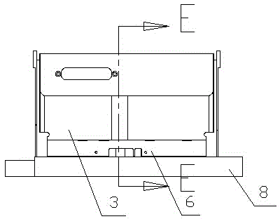
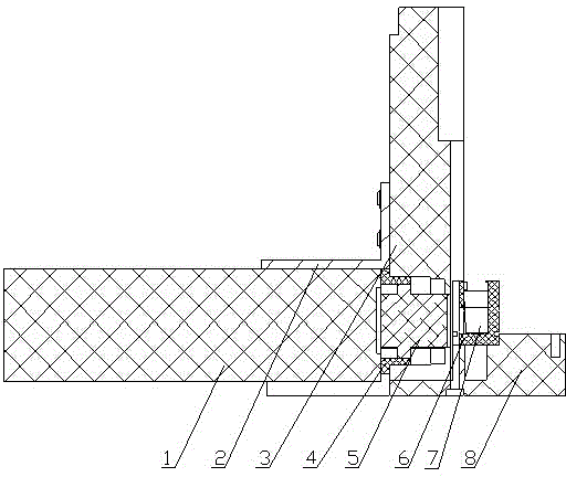
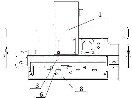
[0019] Such as Figure 1-4 As shown, the present invention discloses an optical fiber conduction device for a chemiluminescence measurement room, which mainly includes three parts: a photomultiplier tube 1, an optical fiber 5, and a cuvette 7, wherein the cuvette 7 is set at the measurement window 1 of the photomultiplier tube 1 On the side, the above-mentioned optical fiber 5 is arranged between the above-mentioned photomultiplier tube 1 and the cuvette 7, and one end of the above-mentioned optical fiber 5 is close to the measurement window of the above-mentioned photomultiplier tube 1, and the oth...


PUM


Abstract

The invention provides an optical fiber conduction device in a chemical light emission measuring chamber. The optical fiber conduction device comprises a photomultiplier and a reaction cup opposite to the photomultiplier, wherein the reaction cup is arranged on one side of a measuring window of the photomultiplier; an optical fiber is arranged between the photomultiplier and the reaction cup; one end of the optical fiber is close to the measuring window of the photomultiplier; the other end of the optical fiber is close to a light emission area of the reaction cup. According to the optical fiber conduction device in the chemical light emission measuring chamber, the optical fiber for light conduction is additionally arranged at the measuring window of the photomultiplier and the light emission area of the reaction cup, the optical path difference caused by the distance from the light emission area of the reaction cup to the measuring window of the photomultiplier is reduced, the measurement errors caused by the optical path difference are reduced, and the measurement result is relatively accurate and stable.

Description

technical field [0001] The invention belongs to the field of medical equipment, and in particular relates to an optical fiber conduction device for a chemiluminescence measurement room. Background technique [0002] Most of the currently commonly used chemiluminescence optical measurement modules use photomultiplier tubes to directly collect photons and amplify them before counting them. These existing chemiluminescence optical measurement modules do not take into account the distance between the luminescent object and the photomultiplier tube. The resulting optical path difference causes deviations in the final measurement results. Contents of the invention [0003] Aiming at the above-mentioned defects in the prior art, the present invention provides an optical fiber guide device for a chemiluminescence measurement chamber with small measurement errors. [0004] The technical solution of the present invention: a fiber optic conduction device for a chemiluminescence meas...

Claims


Application Information

Patent Timeline
IPC IPC(8): G01N21/01G01N21/76
Inventor 吴冬
Owner SUZHOU HYBIOME BIOMEDICAL ENG CO LTD
Why Eureka
Try Eureka