
Position calibration device and method based on LED visible light source

A technology of visible light and light source, applied in measuring devices, instruments, surveying and mapping and navigation, etc., can solve problems such as unusable

Inactive Publication Date: 2015-04-29
张炯
View PDF5 Cites 8 Cited by
  • Summary
  • Abstract
  • Description
  • Claims
  • Application Information

AI Technical Summary

Problems solved by technology

However, the above technologies cannot be conveniently used in smaller ranges (positioning within 10 meters) and indoor environments (GPS signals are generally unreceivable indoors) due to positioning errors and limitations of the use environment.

Method used


Image

  • Position calibration device and method based on LED visible light source
  • Position calibration device and method based on LED visible light source
  • Position calibration device and method based on LED visible light source

Examples


Embodiment Construction

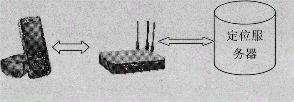
[0016] The specific implementation content includes geographic information server and geographical and positioning data organization; using coded and modulated LED visible light generating devices to mark different geographic locations in the site to be located; deploying wireless network access points in the site; Write software on the computer (smart terminal) to realize geographic information display and positioning functions.

[0017] Geographic Information Server and Organization of Geographic and Positioning Data

[0018] The performance of the hardware device of the geographic information server is determined by the amount of positioning data, the number of terminals served at the same time, etc., and then the appropriate model is selected. After the model is determined, the database service software will run on it. Geographical and positioning data will be stored in the database according to a certain organization. The positioning data mainly refers to the position i...


PUM


Abstract

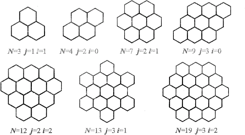
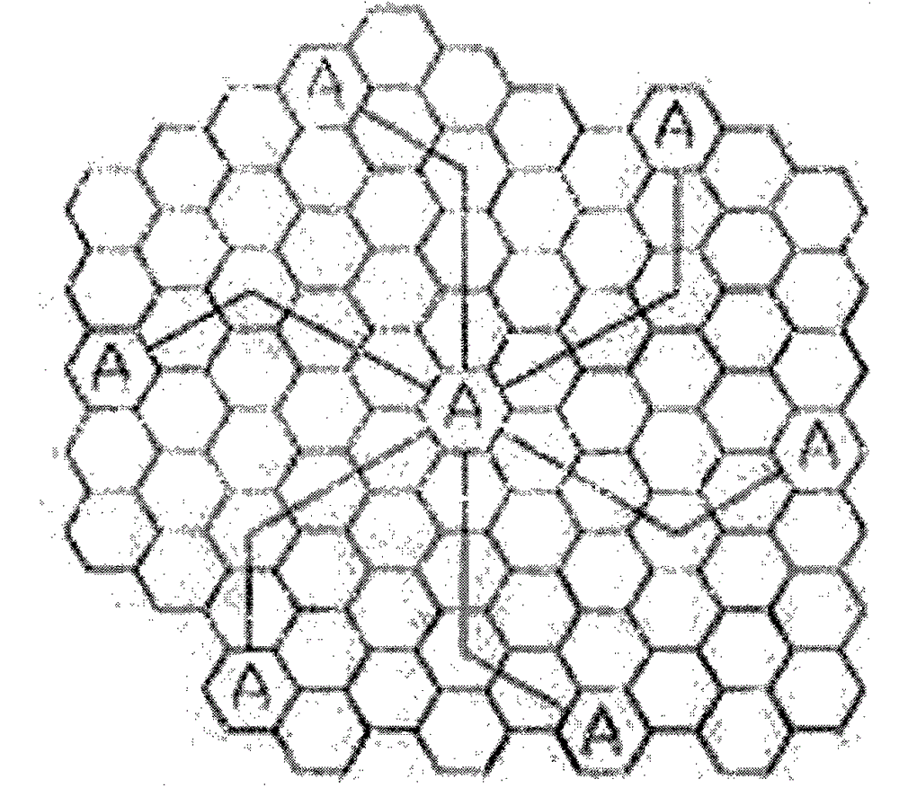
The invention provides a position calibration device and method based on an LED visible light source and relates to a device which is used for forming a honeycomb-shaped array by a location-coded LED visible light source (a visible light emitting device), is arranged in a field needing positioning services, and is used for receiving a visible light signal by holding a visible light terminal so as to realize a positioning function. The device comprises hardware equipment including terminal equipment, the LED visible light source, a geographic information server, a wireless accessing point and the like, and also comprises corresponding software operating on intelligent terminal equipment and the geographic information server. All the equipment can commonly realize the functions, such as visible light signal acquisition and processing, position inquiring and display, calculation and display of a shortest path between two points, and calculation and display of an optimal accessing path among a plurality of points.

Description

technical field [0001] The present invention relates to technical fields such as signal coding, modulation method, signal processing, calibration array organization, computer graphics, etc., and particularly relates to a honeycomb array composed of coded and modulated LED visible light source signal generating devices, so as to realize position resolution in A technology and method for marking the left and right positions of a cavity. Background technique [0002] There are many ways to provide positioning services on smart terminals, and now the more common methods are satellite positioning and AGPS methods to determine the current position of the terminal holder. However, the above technologies cannot be conveniently used in a small range (positioning within 10 meters) and indoor environments (GPS signals are generally unable to be received indoors) due to positioning errors and limitations of the use environment. However, how to provide a sufficiently accurate positionin...

Claims


Application Information

Patent Timeline
Patent Type & Authority Applications(China)
IPC IPC(8): G01C21/00
CPCG01C21/00
Inventor 张炯
Owner 张炯
Learn More