
Fibre Channel Switch that enables end devices in different fabrics to communicate with one another while retaining their unique Fibre Channel Domain_IDs

a fibre channel switch and fibre channel domain technology, applied in data switching networks, multiplex communication, instruments, etc., can solve the problems of inefficiency, high cost, and inability to directly communicate with storage devices in the second san, and achieve the effect of avoiding the loss of data, avoiding loss, and avoiding loss

Active Publication Date: 2005-02-17
CISCO TECH INC
View PDF99 Cites 239 Cited by
  • Summary
  • Abstract
  • Description
  • Claims
  • Application Information

AI Technical Summary

Benefits of technology

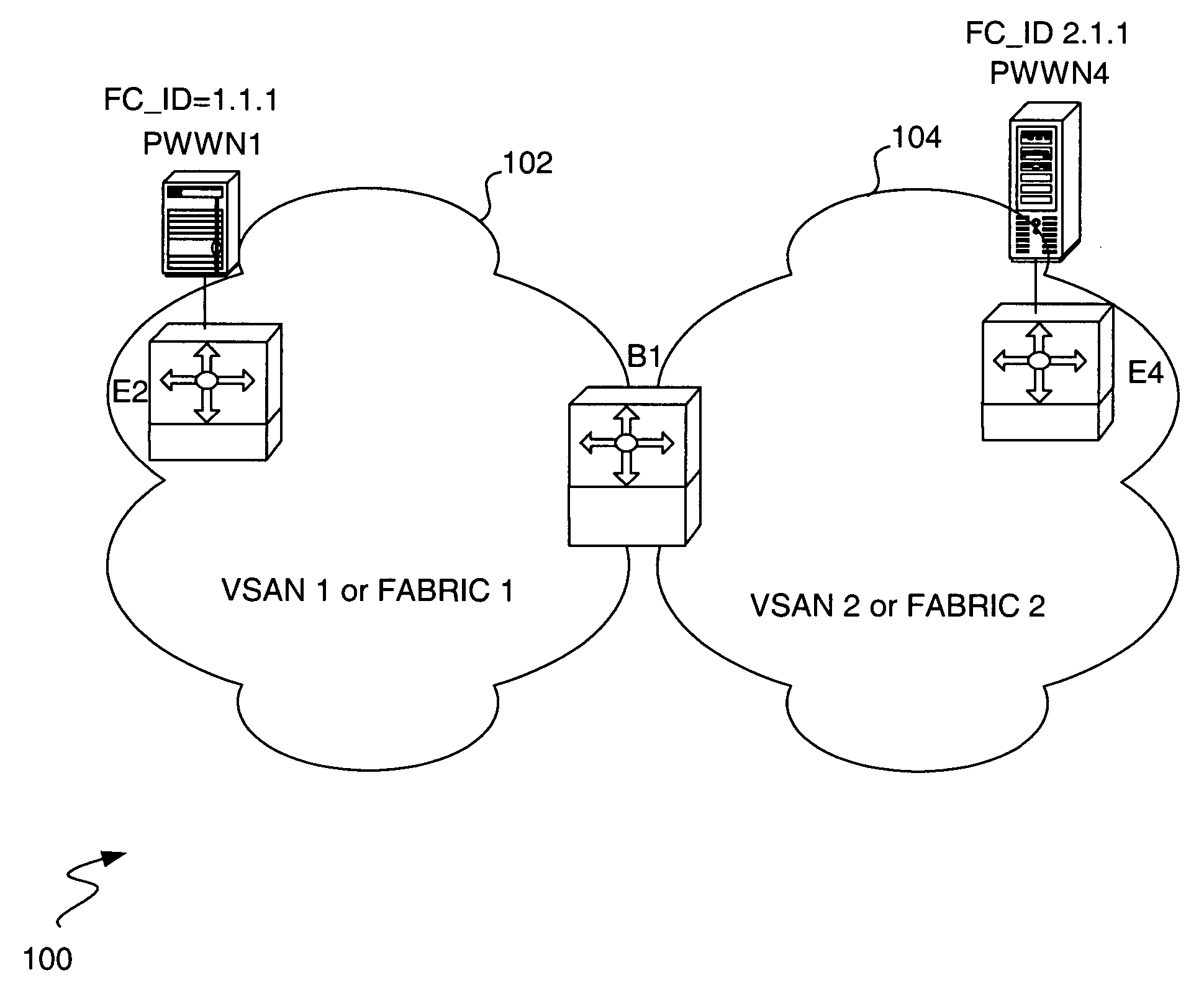
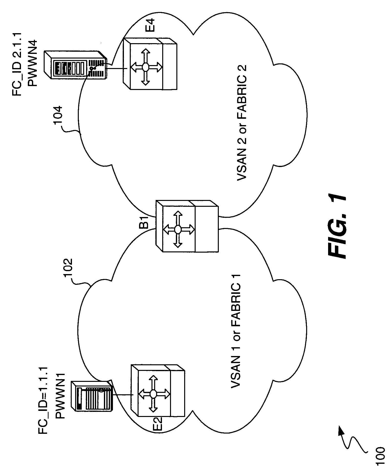
The present invention provides a Switch that allows different fabrics of end devices to communicate with each other while keeping their unique Fibre Channel Domain_IDs. The Switch is connected to two fabrics, and it enables communication between the end devices of the first fabric and the second fabric using their unique Domain_IDs. This allows for seamless communication between different VSANs or physical fabrics.

Problems solved by technology

There is no way that a Host in one SAN can directly communicate with a storage device in a second SAN.
This arrangement is not only inefficient, it is expensive.
Since storage devices cannot be shared among SANs, separate storage devices are required for each SAN.
One problem with this approach is that the border Switches between the VSANs perform FC_ID translations (i.e., Network Address translations or NATs) for the source and destination end devices.
This solution also does not work if encryption or a proprietary protocol is used between the source and destination end devices because there is no way for the border Switches to process the proprietary payloads or de-crypt the frames to identify the source and destination FC_IDs.

Method used


Image

  • Fibre Channel Switch that enables end devices in different fabrics to communicate with one another while retaining their unique Fibre Channel Domain_IDs
  • Fibre Channel Switch that enables end devices in different fabrics to communicate with one another while retaining their unique Fibre Channel Domain_IDs
  • Fibre Channel Switch that enables end devices in different fabrics to communicate with one another while retaining their unique Fibre Channel Domain_IDs

Examples


examples

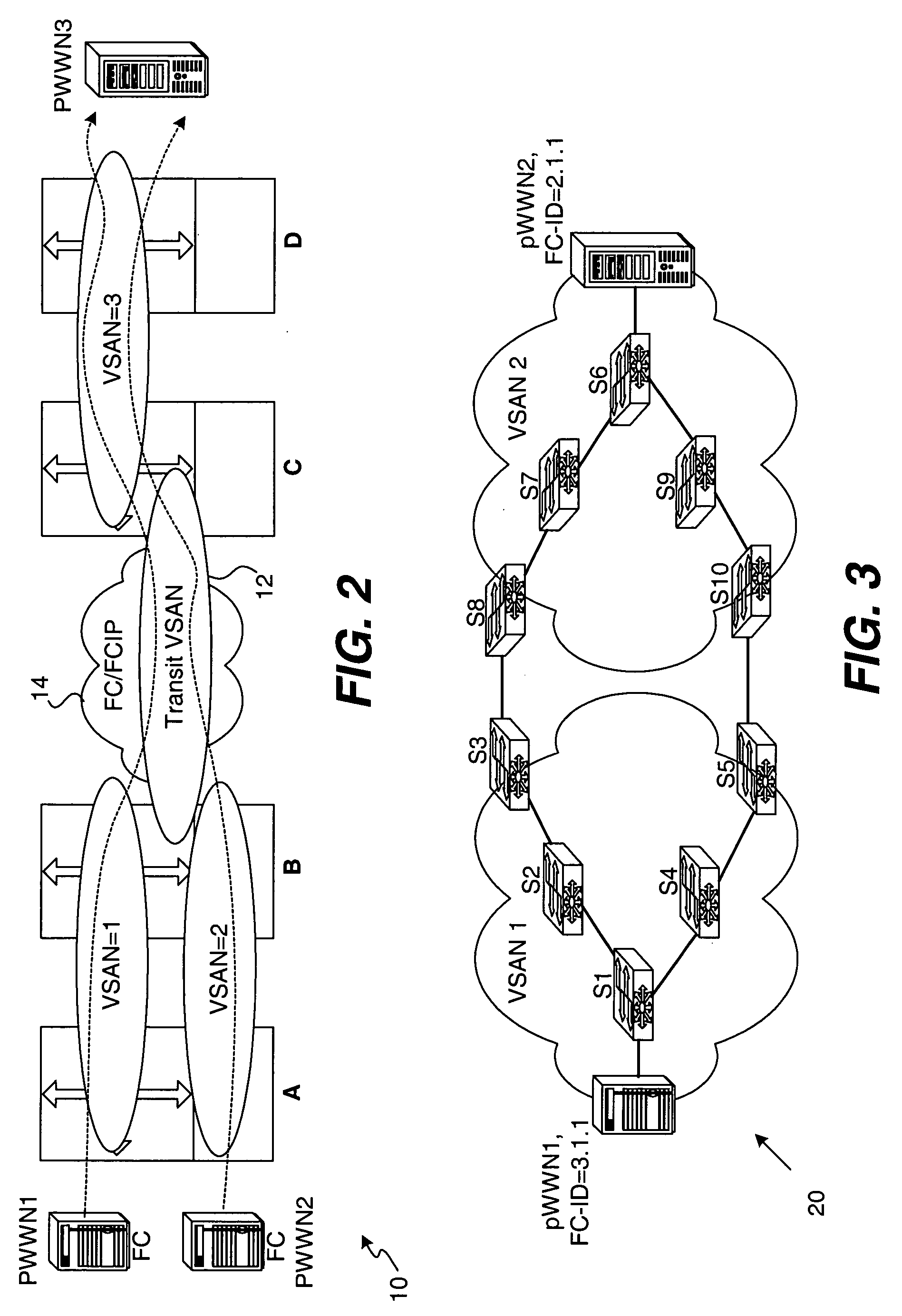
[0072]FIG. 7 presents a scenario where two devices, pWWN1 and pWWN2, need to communicate with a storage device pWWN3. The communication between pWWN2 and pWWN3 is similar to the other scenarios that have been discussed previously and therefore will not be discussed in detail herein. However, consider the case of pWWN1 communicating with pWWN3 where there is not a direct connection between the Border Switches of VSAN 2 and VSAN 3. FIG. 7 illustrates two subcases of this topology, when the two transit VSANs are the same and when they are not the same.

[0073] When the transits VSANs are the same, in order to have pWWN1 communicate with pWWN3, an Inter-VSAN zone is defined containing the two devices. There must be one or more links connecting switches S2 and S3 that carry the Transit VSAN traffic. If the link between the switches is not direct, all the switches in the path between S2 and S3 must carry the transit VSAN.

[0074] When the transit VSANs are not the same, the Inter-VSAN zones...


PUM


Abstract

An Fibre Channel Switch which enables end devices in different Fabrics to communicate with one another while retaining their unique Fibre Channel Domain_IDs. The Switch is coupled to a first fabric having a first set of end devices and a second fabric having a second set of end devices. The Switch is configured to enable communication by the first set of end devices associated with the first fabric with the second set of end devices associated with the second set of end devices using the unique Domain_IDs of each of the first set and the second set of end devices. In one embodiment of the invention, the first and second fabrics are first and second Virtual Storage Array Networks (VSANs) respectively. In an alternative embodiment, the first fabric and the second fabric are separate physical fabrics.

Description

RELATED APPLICATIONS [0001] The present invention is a Continuation-in-Part of co-pending, commonly assigned, application Ser. No. 10 / 034,160 filed Dec. 26, 2001 and entitled “Methods and Apparatus for Encapsulating a Frame for Transmission in a Storage Area Network”, incorporated herein for all purposes.BACKGROUND OF THE INVENTION [0002] 1. Field of the Invention [0003] The present invention relates to storage area networks, and more particularly, to a Fibre Channel Switch that enables the end devices in different Fabrics to communicate with one another while retaining their unique Fibre Channel IDs. [0004] 2. Background of the Invention [0005] With the increasing popularity of Internet commerce and network centric computing, businesses and other organizations are becoming more and more reliant on information. To handle all of this data, storage area networks or SANs have become very popular. A SAN typically includes a number of storage devices, a plurality of Hosts, and a number o...

Claims


Application Information

Patent Timeline
Patent Type & Authority Applications(United States)
IPC IPC(8): H04L12/28H04L12/44G06F13/10H04L12/46H04L12/56H04L45/74
CPCH04L45/00H04L67/1097H04L2212/0025H04L2212/00H04L45/04H04L45/74H04L49/357
Inventor DUTT, DINESH G.EDSALL, THOMASJAIN, ANKURGAI, SILVANOBANERJEE, SUBRATABERGAMASCO, DAVIDERAIMONDO, BRUNOBHARADWAJ, RAJEEV
Owner CISCO TECH INC
Learn More