
Flat gate valve

A flat gate valve and pressure relief technology, which is applied in the direction of sliding valves, valve devices, engine components, etc., can solve the problems of valve plate distortion and increased working strength, and achieve the effects of reducing extrusion, easy switching operations, and good results

Inactive Publication Date: 2015-04-29
CHENGDU XUNDE SCI & TECH
View PDF6 Cites 1 Cited by
  • Summary
  • Abstract
  • Description
  • Claims
  • Application Information

AI Technical Summary

Problems solved by technology

However, when the control valve is opened, the pressure of the liquid on the valve plate will be different due to the liquid flowing from the upstream pipeline due to the difference in the opening height of the valve plate, that is, the pressure of the liquid on the upper part of the valve plate is greater than the pressure of the liquid on the lower part, thus It is easy to cause the valve plate to be twisted and deformed; and in order to lift or lower the valve plate, it is necessary to use a certain force to operate the switch. At this time, the valve plate is squeezed by the pressure of the left and right valve seats. Or more force is required to close the valve plate, resulting in an increase in working strength

Method used


Image

  • Flat gate valve
  • Flat gate valve

Examples


Embodiment 1

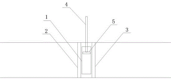
[0014] Example 1 as figure 1 As shown, the implementation of a pressure-relief flat gate valve includes a valve seat, a gate 1 and a valve stem 4. The valve seat is divided into a first valve seat 2 and a second valve seat 3, and the gate 1 and the second valve seat The first valve seat 2 and the second valve seat 3 are tightly fitted through a sealing ring. One end of the valve stem 4 is connected to the gate plate 1, and the other end is connected to a twist switch. The rotation of the knob switch drives the valve stem 4 to rotate, thereby driving the valve plate 1 to rise or fall.

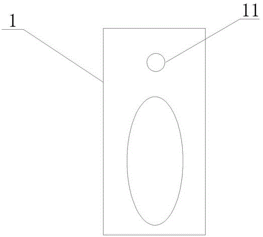
[0015] Such as figure 2 As shown, the gate 1 is provided with a cavity and a through hole 11, and a pressure relief component 5 is provided in the cavity, and the pressure relief component 5 is connected with the valve stem 4 through a screw rod. There is one through hole 11 , which is opened on any side of the valve plate 1 . The side of the through hole 11 close to the first valve seat 2 a...

Embodiment 2

[0016] Embodiment 2 The difference between this embodiment and Embodiment 1 is that there are two through holes 11 on the valve plate 1, which are distributed on both sides of the valve plate 1 respectively. The holes 11 protrude and retract in two directions, so as to achieve the purpose of pressure relief.


PUM


Abstract

The invention discloses a flat gate valve capable of decompression. The flat gate valve capable of decompression comprises a valve seat, a gate plate and a valve rod, wherein the valve seat comprises a first valve seat and a second valve seat; the gate plate is tightly matched with the first valve seat and the second valve seat; one end of the valve rod is connected with the gate plate, and the other end of the valve rod is connected with a rotary switch. The flat gate valve capable of decompression is characterized in that a concave cavity and a through hole are formed in the gate plate, a decompression component is arranged in the concave cavity and can stretch out of or get back in the through hole, and the valve rod is connected with the decompression component through a transmission component. According to the technical scheme, a decompression technical effect can be realized by the flat gate valve capable of decompression, thus the operation of opening and closing the flat gate valve capable of decompression can be easily completed by working personnel, and a good function of relieving the extrusion, on a valve plate, of liquid during an opening / closing process and preventing the valve plate from twisting and deforming is obtained.

Description

technical field [0001] The invention relates to the field of mechanical manufacturing, in particular to a pressure-relieving slab gate valve. Background technique [0002] Slab gate valves are now widely used in pipelines for refined oil products, pipelines with suspended particle media, and other pipelines. The advantages of the flat gate valve itself, such as high sealing performance, convenient operation and simple structure, are the key to its continuous recognition. However, when the control valve is opened, the pressure of the liquid on the valve plate will be different due to the liquid flowing from the upstream pipeline due to the difference in the opening height of the valve plate, that is, the pressure of the liquid on the upper part of the valve plate is greater than the pressure of the liquid on the lower part, thus It is easy to cause the valve plate to be twisted and deformed; and in order to lift or lower the valve plate, it is necessary to use a certain forc...

Claims


Application Information

Patent Timeline
Patent Type & Authority Applications(China)
IPC IPC(8): F16K3/02F16K3/30
CPCF16K3/02F16K3/30
Inventor 龚素华
Owner CHENGDU XUNDE SCI & TECH
Learn More