
Electric controlled assembly of combination pump

A combined pump and electronic control technology, used in engine components, machines/engines, charging systems, etc., can solve the problem of not being able to control the injection rate and injection pressure, not directly changing the fuel volume and timing, and the large volume of the solenoid valve assembly. and other problems, to achieve the effect of simplifying the oil pump structure and intermediate links, fast conduction, and convenient transformation

Inactive Publication Date: 2008-03-12
成都威特电喷有限责任公司
View PDF4 Cites 0 Cited by
  • Summary
  • Abstract
  • Description
  • Claims
  • Application Information

AI Technical Summary

Problems solved by technology

However, it can only perform position control, and cannot directly change the fuel volume and timing. Since it does not change the original fuel injection device and fuel injection characteristics, it cannot regulate the fuel injection rate and fuel injection pressure.
At the same time, there are many intermediate links and slow system control response.
However, the unit pump used in the diesel injection system by the German Bosch (Doctor) company cannot be directly inserted into the existing P-type pump chamber, so the fuel injection pump assembly formed by it not only needs to completely discard the pump body of the original diesel engine , and the volume is relatively large, especially its square solenoid valve assembly is not only large in size, complicated in manufacturing process, but also inconvenient to install

Method used


Image

  • Electric controlled assembly of combination pump
  • Electric controlled assembly of combination pump

Examples


Embodiment Construction

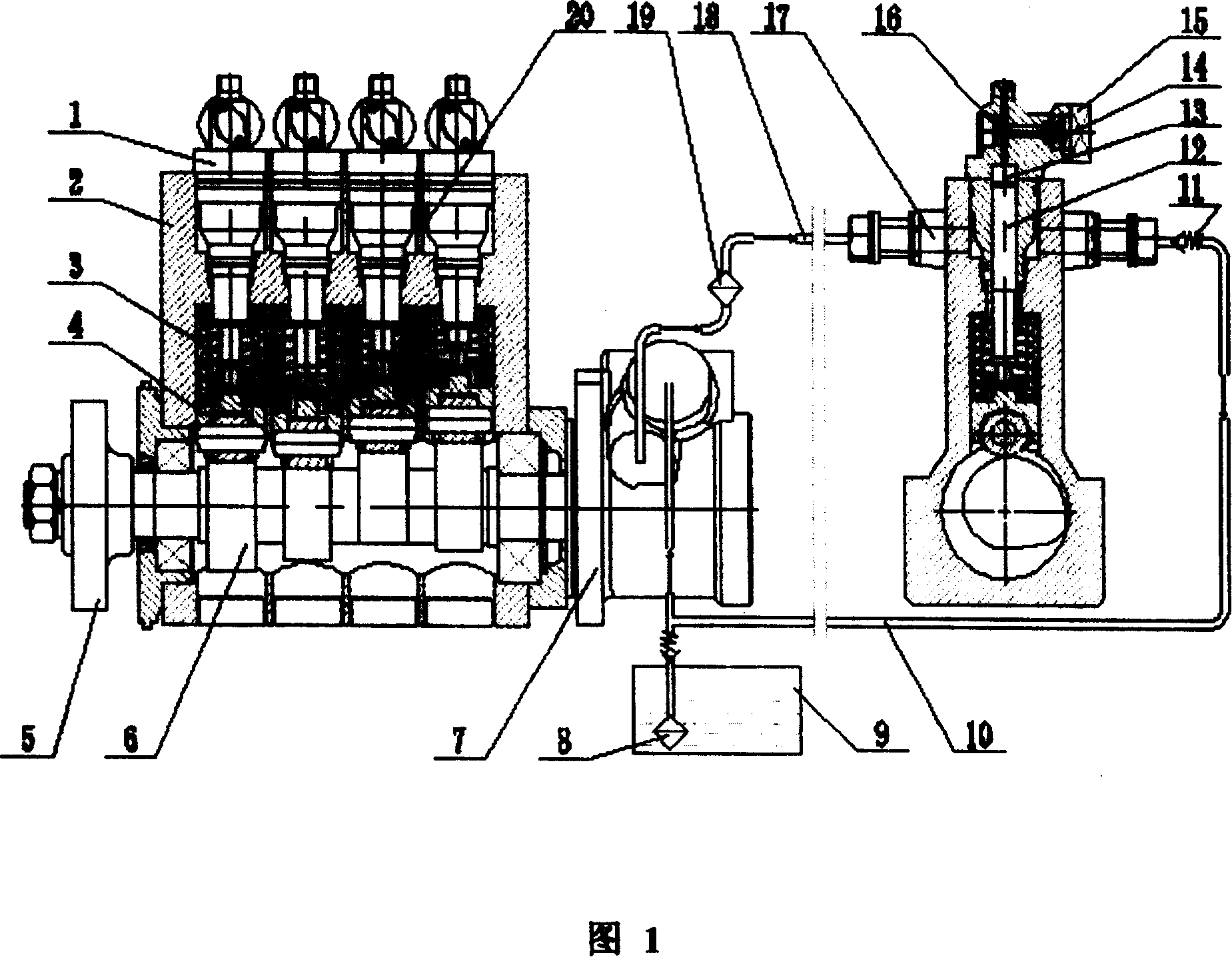
[0012] Fig. 1 is a schematic diagram of the structure of the electric control combined pump assembly, which is that the number of pump bodies 1 can be 4, 6 or 8, and only 4 pump bodies are shown in this accompanying drawing. The pump chamber used may be the pump chamber of a P-type pump.

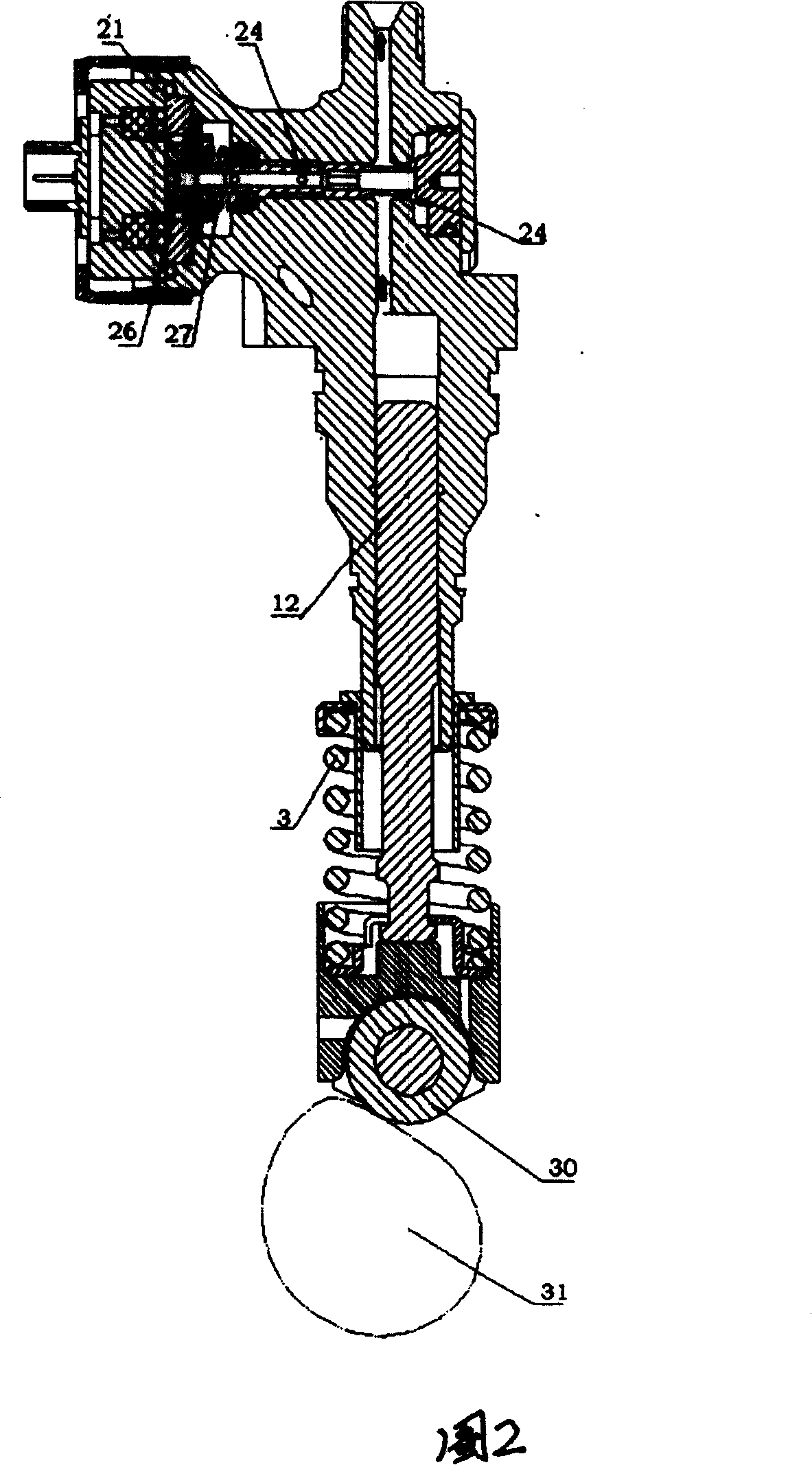
[0013] In the schematic diagram of Fig. 1, the pump body 1, pump chamber 2, spring 3, roller and tappet assembly 4, coupling plate 5, camshaft 6, fuel delivery pump 7 and other auxiliary pumps of the electric control combination pump with in-line discharge are mainly described. An embodiment of an electronically controlled combination pump assembly composed of parts. Wherein the pump body 1 is mainly used for installing the plunger 12, the valve stem assembly 16 and the solenoid valve 15, etc., and a plunger hole and a valve stem hole are formed on the top of the pump body. In the middle of the pump chamber, there are interconnected inlet and outlet oil passages 17, 20. The camshaft 6 is i...


PUM


Abstract

The present invention discloses an electrically-controlled combined pump assembly whch can be hung on the exterior of engine cylinder body. Said invention includes electrically-controlled combined pump body which is in-line arranged and can be driven by cam shaft and pump chamber in which the above-mentioned pump body can be mounted. The described electrically-controlled combined pump has a circular electromagnetic valve component for controlling high-pressure fuel circuit and low-pressure fuel circuit, also includes valve rod component connected together with electromagnetic valve component and pump body with channels respectively communicated with high and low pressure fuel circuits.

Description

technical field [0001] The invention relates to an electric control combination pump assembly installed in a fuel injection system of a diesel engine. Background technique [0002] In the fuel injection pump assembly used in the diesel injection device in the known technology, in order to realize the control of the oil quantity, the oil return helical chute is usually formed on the plunger, so that the pull rod or rack can be pulled by the governor installed on it. The relative position of the spiral chute of the rotating plunger and the oil return hole realizes the control of the oil quantity. The control of fuel injection timing is realized by changing the relative position between the crankshaft of the diesel engine and the camshaft of the oil pump through the inertial mechanism (advanced device). Its high-pressure oil outlet and pressure relief process should be regulated by the oil outlet valve at the outlet of the oil pump. The resulting fuel injection pump has a com...

Claims


Application Information

Patent Timeline
Patent Type & Authority Patents(China)
IPC IPC(8): F02M51/04
Inventor 朱元宪余泽唐仁宏徐平涛
Owner 成都威特电喷有限责任公司
Learn More