
A conical bottom tank for oil sand treatment

A technology for conical bottom tanks and oil sands, applied in the petroleum industry, production fluids, boreholes/well components, etc., can solve the problem of reducing the overall safety of conical bottom tanks, large changes in structural shape and size, and affecting the working efficiency of conical bottom tanks and other problems, to achieve the effect of increasing the effective working volume, making the production simple and increasing the production cost

Active Publication Date: 2016-08-17
BC P INC CHINA NAT PETROLEUM CORP +1
View PDF3 Cites 0 Cited by
  • Summary
  • Abstract
  • Description
  • Claims
  • Application Information

AI Technical Summary

Problems solved by technology

[0003] There are mainly the following problems and challenges in the design and use of conical bottom tanks for oil sand treatment: (1) The structural shape and size of the connection between the tank wall and the conical bottom vary greatly, and it is necessary to install a supporting structure on the Ensure a certain space between the conical bottom tank and the ground. These factors will easily lead to local stress concentration of the conical bottom tank and reduce the overall safety of the conical bottom tank
(2) The oil sand deposits in the conical bottom tank are highly viscous, and some oil sands attached to the conical bottom plate cannot be smoothly discharged from the conical bottom tank under the action of gravity load, which will reduce the effective volume of the conical bottom tank , affecting the working efficiency of the conical bottom tank
[0004] The above reasons severely limit the application of conical bottom tanks in the oil sands mining process

Method used


Image

  • A conical bottom tank for oil sand treatment
  • A conical bottom tank for oil sand treatment

Examples


Embodiment 1

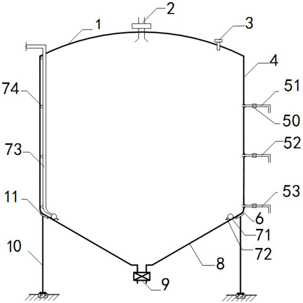
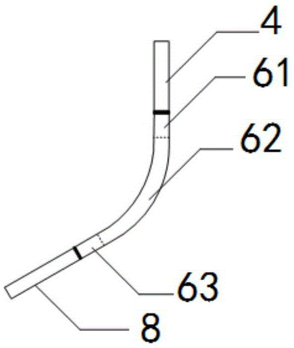
[0026] Embodiment 1: as figure 1 , figure 2 As shown, a conical bottom tank for oil sand treatment,

[0027] In the figure: 1, tank top, 2, oil sand inlet, 3, pressure balance valve, 4, tank wall, 50, throttle valve, 51, upper liquid discharge pipe, 52, middle liquid discharge pipe, 53, lower Drain pipe, 6, arc-shaped cone bottom plate, 61, upper straight plate section, 62, circular arc section, 63, lower straight plate section, 71, ring pipe, 72, nozzle, 73, high-pressure water pipe, 74, pipe clamp, 8 , Straight cone bottom plate, 9, oil sand outlet, 10, support system, 11, reinforcing plate.

[0028] Such as figure 1 As shown, the conical bottom tank for oil sand treatment includes: a tank top 1, a tank wall 4, and a straight conical bottom plate 8, the top of the tank wall 4 is connected to the tank top 1, and the bottom end of the tank wall 4 passes through an arc-shaped conical bottom plate 6 It is connected with the top of the straight cone bottom plate 8, and the b...


PUM

PropertyMeasurementUnit
thicknessaaaaaaaaaa
diameteraaaaaaaaaa
heightaaaaaaaaaa

Abstract

The invention discloses a conical bottom tank for oil sand treatment, and belongs to the technical field of oil-gas resource exploitation. The top end of a tank wall is connected with a tank top; the bottom end of the tank wall is connected with the top end of a straight conical bottom plate through an arc conical bottom plate; an oil sand feeding opening is formed in the center position of the tank top; a pressure balancing valve is arranged at the position, close to the tank wall, on the tank top; an oil sand outlet is formed in the bottom end of the straight conical bottom plate; the arc conical bottom plate comprises an upper straight plate segment, an arc segment and a lower straight plate segment; the bottom of the upper straight plate segment is connected with the top of the arc segment; the bottom of the arc segment is connected with the top of the lower straight plate segment; the upper straight plate segment is connected with the bottom of the tank wall; the lower straight plate segment is connected with the upper part of the straight conical bottom plate; an upper drain pipe is arranged at the position of 2 / 3 height of the tank wall; a throttle valve is arranged on the upper drain pipe; a middle drain pipe is arranged at the position of 1 / 3 height of the tank wall; another throttle valve is arranged on the middle rain pipe; and a lower drain pipe is arranged at the bottom position of the tank wall. The conical bottom tank can be widely applied to other fields, such as storage of grain and cement.

Description

technical field [0001] The invention relates to a cone-bottom tank for oil sand treatment, which belongs to the technical field of oil and gas resource development. Background technique [0002] Oil sand (Oil Sand) is also known as "tar sand", "heavy oil sand" or "tar sand". It looks like black molasses, and its extraction method is very different from traditional oil extraction. Simply put, oil sands mining is "digging" for oil, not "extracting" it. The sandstone impregnated with heavy residual oil that has been exposed or near the surface is the product of asphalt-based crude oil that loses light components during the migration process. Due to the emphasis on environmental protection at this stage, open-pit oil sand mining has been gradually eliminated. At this stage, SAGD (SteamAssisted Gravity Drainage) technology is mainly used to melt heavy oil such as asphalt in oil sands by injecting hot steam into oil sand deposits, and then pump up the melted liquid through elec...

Claims


Application Information

Patent Timeline
Patent Type & Authority Patents(China)
IPC IPC(8): C10G1/00E21B43/34
CPCC10G1/00E21B43/34
Inventor 辛敏东李明刘伟曹学文王同涛张俊
Owner BC P INC CHINA NAT PETROLEUM CORP
Learn More