
Safety belt device and safety belt winder

A technology for a seat belt retractor and an installation column, which is applied to belt tensioners and other directions, can solve problems such as the complex structure of the seat belt retractor, and achieve the effects of simple structure, small occupied space, and small number of parts.

Active Publication Date: 2015-04-29
BYD CO LTD
View PDF6 Cites 4 Cited by
  • Summary
  • Abstract
  • Description
  • Claims
  • Application Information

AI Technical Summary

Problems solved by technology

[0005] In order to solve the problem of complex structure of the existing seat belt retractor, the embodiment of the present invention provides a seat belt retractor and its seat belt device

Method used


Image

  • Safety belt device and safety belt winder
  • Safety belt device and safety belt winder
  • Safety belt device and safety belt winder

Examples


Embodiment 1

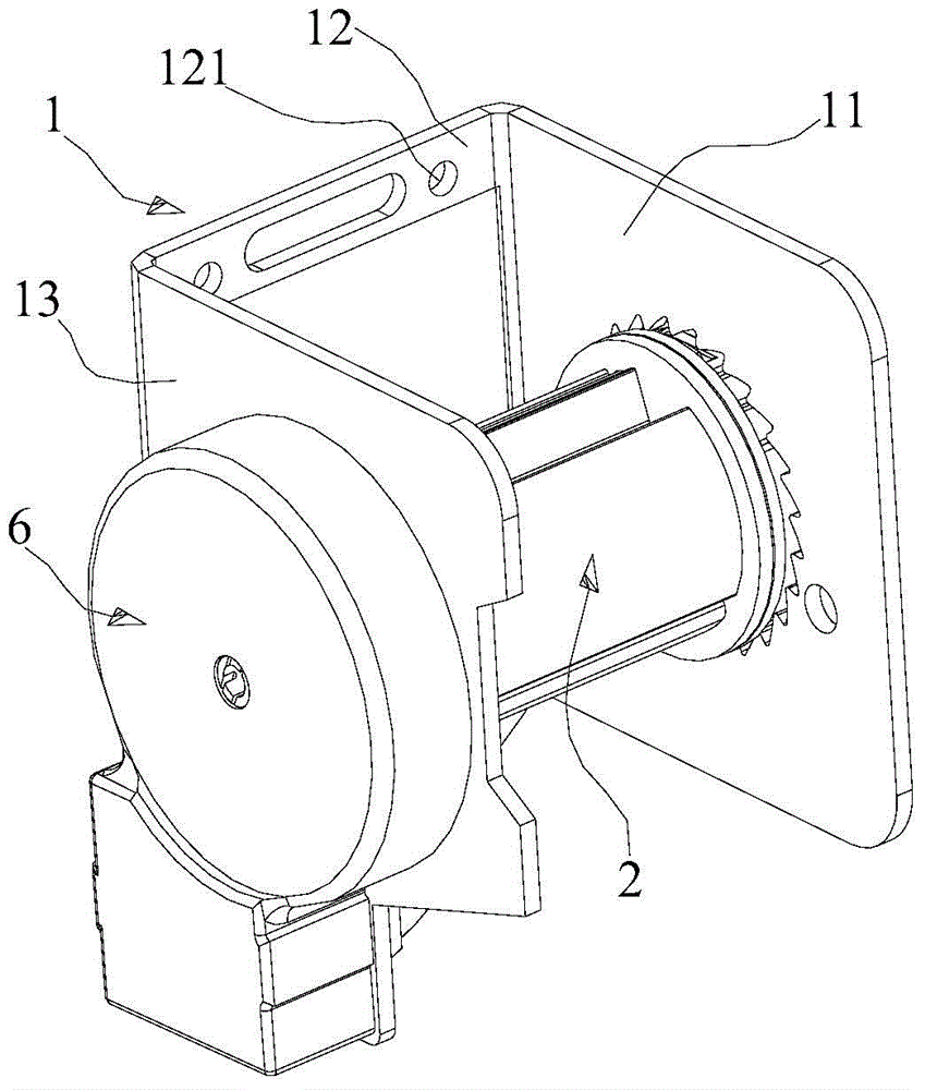
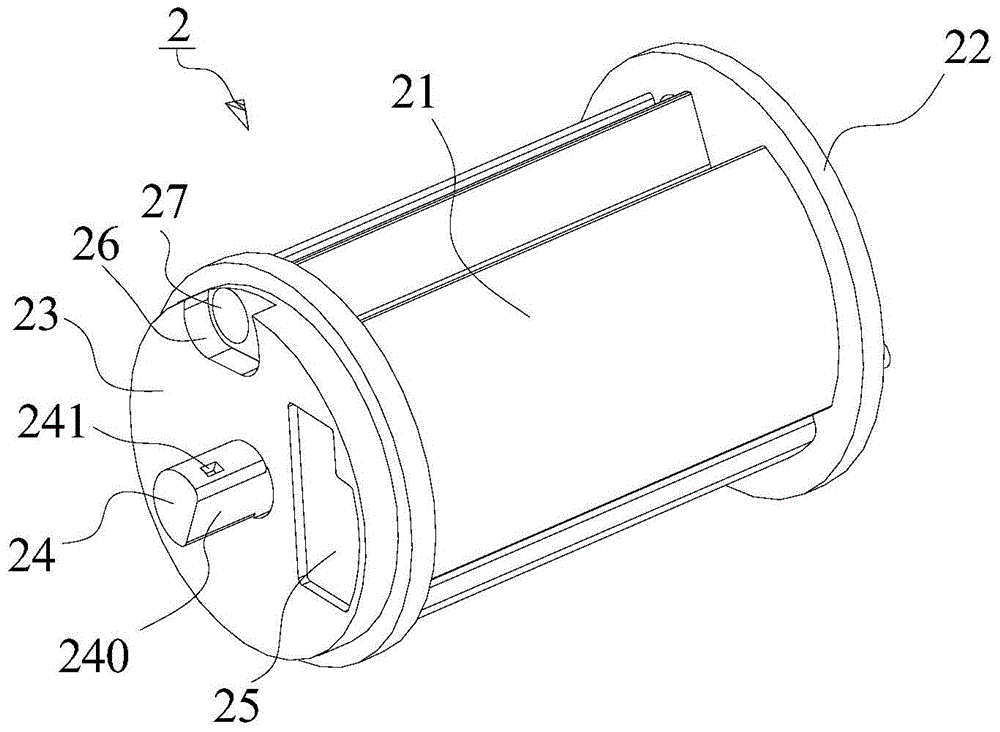
[0059] In this example, the seat belt retractor will be described in detail. To make the subsequent description more concise and clear, pulling the webbing inward to tighten the webbing is referred to as winding the webbing or pulling back the webbing, and pulling the webbing out to release the webbing is referred to as Release the webbing or pull out the webbing, such as figure 1 The overall three-dimensional schematic diagram of the seat belt retractor given, and figure 2 The disassembled schematic diagram of the safety belt retractor is given, which includes the reel 2, the frame 1, the ratchet 3, the locking device, and the switching device 4; for the convenience of description, the S2 direction in the figure is defined as the right side, and the S1 direction is defined as the left side .

[0060] During the research and development process, the inventor found that the existing safety belt retractor adopts a complex structure scheme to realize its ALR and ELR functions, ...

Embodiment 2

[0096] This example provides a seat belt device, including the seat belt retractor mentioned in the foregoing embodiment 1, a webbing wound on the reel 2 of the seat belt retractor, and slidably arranged on the webbing The tongue on the top, and the buckle that is arranged on the vehicle body or the vehicle seat and fastened with the tongue.

[0097] Because the seat belt retractor has been specifically introduced in Embodiment 1, and the webbing, tongue, buckle, etc. are well known to those skilled in the art, therefore, no more details are given.

[0098] Likewise, with the seat belt device provided in this example, since it includes the innovative seat belt retractor in Embodiment 1, the seat belt device can effectively switch between the ALR mode and the ELR mode. The structure is simpler, the number of parts is small, the cost is low, and the occupied space is small. Material costs and assembly costs are lower.


PUM


Abstract

In order to solve the problem of complex structure of a traditional safety belt winder, the invention provides a safety belt winder and a safety belt device thereof. The safety belt winder comprises a winding shaft, a frame, a ratchet wheel, a locking device and a switching device, wherein the switching device comprises a transmission wheel and an automatic locking rod; as the transmission wheel is eccentrically connected with a pin column, when the winding shaft rotates, the winding shaft can drive the transmission wheel to eccentrically rotate; a first switching pin and a second switching pin are arranged on the transmission wheel; the automatic locking rod comprises a locking jaw, an induction groove and an induction jaw; the locking jaw fits an end surface tooth; and the engagement or the separation of the locking jaw and the end surface tooth is realized through the fit between the first switching pin and the induction groove and the fit between the second switching pin and the induction jaw. The safety belt winder, disclosed by the invention, effectively realizes the switching between an ALR mode and an ELR mode, and has the advantages of simpler structure, small part number, low cost, small occupied space and lower material cost and assembly cost.

Description

technical field [0001] The invention relates to a safety belt device on an automobile, in particular to the field of a safety belt retractor. Background technique [0002] For the sake of safety, the car seat belt is an essential part of the vehicle. The existing seat belt device generally includes a seat belt retractor installed in the car body, and the seat belt (or webbing) is placed in the retractor , to pull the webbing inward to recover the webbing or pull the webbing outward to release the webbing. The existing common seat belt retractors all have ELR (full name in English: Emergence Locking Retractor, Chinese name: Emergency Locking Retractor). The retractor equipped with ELR triggers the action of the locking mechanism after sensing the webbing pulling speed or the acceleration or deceleration of the vehicle through the response of the sensor, preventing the reel from rotating in the direction of webbing pulling, thereby achieving the effect of protecting the vehicl...

Claims


Application Information

Patent Timeline
Patent Type & Authority Applications(China)
IPC IPC(8): B60R22/34B60R22/36
CPCB60R22/36
Inventor 李光
Owner BYD CO LTD
Learn More