
Ventilated condensing device of water tank type cleaning machine

The technology of a sink type washing machine and a condensing device is applied in the direction of the washing machine/rinsing machine parts of tableware, etc., which can solve the problems of damp cabinets, complicated pipeline structure, occupying space on the outer wall of the sink, etc., so as to improve the utilization rate and simplify the pipeline. Road structure, ensure the effect of drying

Active Publication Date: 2015-04-29
NINGBO FOTILE KITCHEN WARE CO LTD
View PDF9 Cites 16 Cited by
  • Summary
  • Abstract
  • Description
  • Claims
  • Application Information

AI Technical Summary

Problems solved by technology

[0004] In the washing machine mentioned above, the overflow port and the air vent (pressure relief hole) are set independently, that is to say, the openings with different functions need to be set independently, which will lead to a large number of pipelines on the side wall of the sink, which greatly occupies the outer wall of the sink. This not only affects the appearance and cleanliness of the washing machine surface, but also leads to more components and increases the difficulty of manufacturing, and also makes the external pipeline structure more complicated; in addition, because this washing machine is usually set in the cabinet of the user's kitchen , when the hot air is discharged from the pressure relief hole on the side wall of the sink body, it cools after contacting the outside wall of the sink body or the cabinet, and the condensed water remains in this area, which will cause the cabinet to become damp and moldy after long-term use

Method used


Image

  • Ventilated condensing device of water tank type cleaning machine
  • Ventilated condensing device of water tank type cleaning machine
  • Ventilated condensing device of water tank type cleaning machine

Examples


Embodiment Construction

[0022] The present invention will be further described in detail below in conjunction with the accompanying drawings and embodiments.

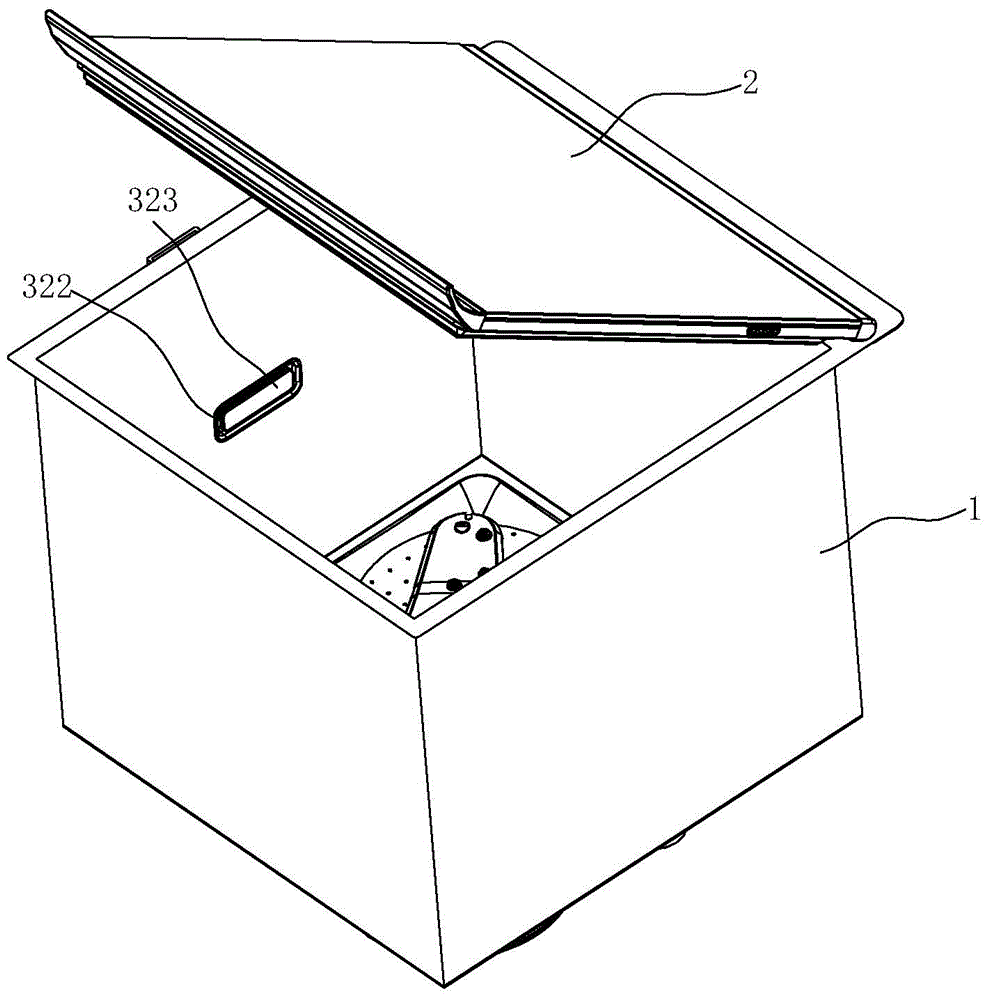
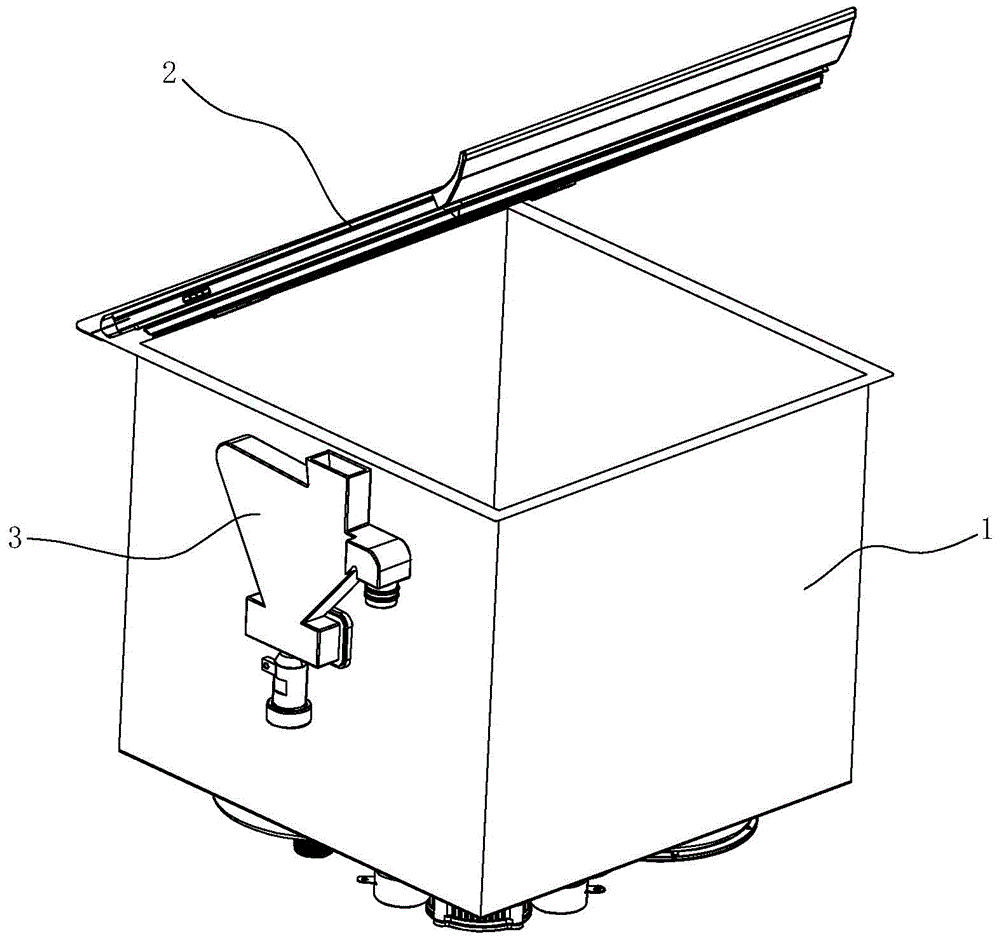
[0023] see figure 1 and figure 2 , a kind of sink type cleaning machine that uses ventilating condensing device of the present invention, can be used for washing dishes, vegetables, fruit etc. 1 can be an ordinary household sink, and the sink body 1 and the cover plate 2 form a washing space to accommodate the above-mentioned dishes, vegetables, fruits, etc., and clean them.

[0024] The sink type cleaning machine is also equipped with a cleaning mechanism, a heating component, an ultrasonic cleaning component, etc. For details, please refer to the disclosure of the applicant’s Chinese patent application number 201320889945.4, and will not be repeated here. Other structures in the prior art may also be adopted for the heating assembly and the cleaning mechanism in the sink type washing machine.

[0025] One side wall of the water tank body...


PUM


Abstract

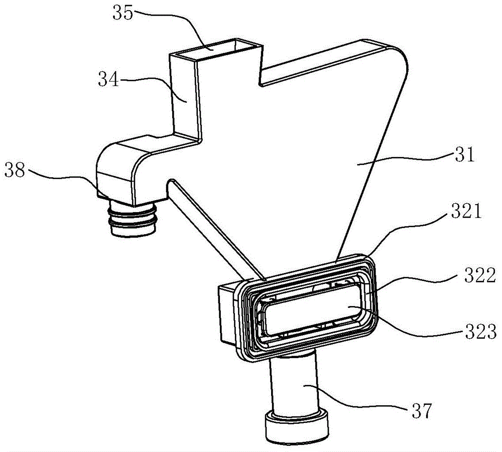
The invention discloses a ventilated condensing device of a water tank type cleaning machine. The ventilated condensing device of the water tank type cleaning machine is arranged on the side wall of the cleaning machine and comprises a pipeline body, a first opening is opened in the pipeline body, a first cavity used for overflowing and communicated with the first opening and a second cavity located above the first cavity and communicated with the inside of the first cavity are formed in the pipeline body, a vent hole is formed in the top of the second cavity, and a baffle plate used for condensing the water vapor in the air flowing to the vent hole from the first cavity to flow back to the first cavity is arranged in the second cavity. The ventilated condensing device of the water tank type cleaning machine organically combines a condensing device with a ventilation device, the hot air can be discharged to an air current pipeline from an overflow cavity, and moreover, the hot air is cooled and condensed in an air current passage, the pipeline structure at the outer wall of the cleaning machine is simplified, the moisture is avoided from discharging to the inside of a cabinet, the moisture can flow back to the cleaning machine, the dryness of the ventilated condensing device is guaranteed, and the dryness of the cabinet is guaranteed.

Description

technical field [0001] The invention relates to a water tank type cleaning machine, in particular to a ventilating condensing device of the water tank type cleaning machine. Background technique [0002] A dishwasher is a device that sprays cold or hot water onto dishes to remove dirt adhering to the dishes and cleans the dishes. The dishes are placed in the dish frame in the dishwashing cabinet. A general dishwasher includes a pump and a nozzle for spraying washing water, a heater for generating hot water, and the like. Today's dishwashers have begun to use steam to clean dishes. Compared with using heated water, using steam also reduces the washing time and improves the washing effect. These dishwashers all have a common shortcoming, that is, the required space is relatively large, and such dishwashers usually require their own independent casing and independent parts, so the general dishwashers are relatively large in size and are not suitable for use. It is used in som...

Claims


Application Information

Patent Timeline
IPC IPC(8): A47L15/42
Inventor 徐慧朱灯光郑峰茅忠群诸永定
Owner NINGBO FOTILE KITCHEN WARE CO LTD
Learn More