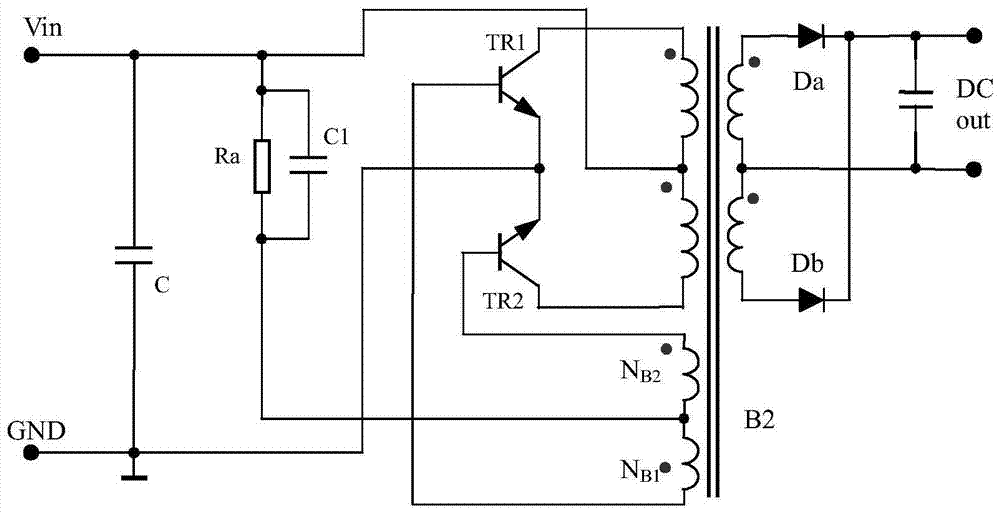
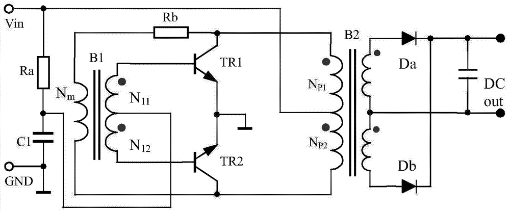
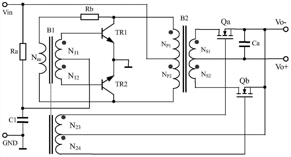
A bias circuit for self-excited push-pull converter
A bias circuit, self-excited push-pull technology, used in output power conversion devices, DC power input conversion to DC power output, instruments, etc., can solve the problem that the efficiency cannot be further improved, and achieve the effect of achieving efficiency
- Summary
- Abstract
- Description
- Claims
- Application Information
AI Technical Summary
Problems solved by technology
Method used
Image
Examples
no. 1 example
[0058] see Figure 4 , Figure 4 It is a functional block diagram of the original technical solution of the present invention, a bias circuit of a self-excited push-forward converter, which is applied to a self-excited push-forward converter including Royer circuit and Jingsen circuit, including a first start-up circuit 11, A second start-up circuit 12, a low-voltage auxiliary power supply 13, and a first diode D1;
[0059] The first start-up circuit 11 is the start-up circuit of the original self-excited push-forward converter, including at least one first capacitor, and the input end connected to the working voltage Vin of the self-excited push-forward converter is no longer connected to the input working voltage The input end of the first start-up circuit 11 is connected to the cathode of the first diode D1;
[0060] The low-voltage auxiliary power supply 13 includes: an auxiliary winding N wound on the main transformer B2 A , the second diode D2, and the second capacito...
no. 2 example
[0088] see Figure 4 , Figure 4 It is a functional block diagram of the original technical solution of the present invention, and the connection relationship is the same as that of Embodiment 1, and will not be repeated here.
[0089] Figure 6 The specific circuit of the second embodiment is given, the above Figure 4 In the original technical solution, the second start-up circuit 12 in the second embodiment includes: a first triode Q1, a second triode Q2, a third triode Q3, and a first resistor R1, a second resistor R2 , the third resistor R3, the fourth resistor R4, and the fifth resistor R5, wherein the first triode Q1 and the third triode Q3 are of PNP type, and the second triode Q2 is of NPN type, and their connection relationship is: The emitter of the first triode Q1 is connected to the emitter of the third triode Q3, the connection point is also connected to one end of the fifth resistor R5, the connection point forms the input end of the second start-up circuit, ...
no. 3 example
[0111] see Figure 8 , Figure 8 still obey Figure 4 The connection relationship of the original technical solution, in Example 1, is used to describe Figure 4 Connections still apply to Figure 8 connection relationship.
[0112] Here we focus on the corresponding scheme three Figure 8 The connection relationship and working principle of the scheme:
[0113] Figure 8 It appears to be very simple, and the third scheme of the second start-up circuit 12 includes: the first triode Q1, the first resistor R1, the second resistor R2, the third resistor R3, and an optocoupler N1, wherein the first triode The tube is PNP type, and its connection relationship is: the emitter of the first triode Q1 is connected to the collector of the optocoupler N1, and the connection point forms the input end of the second start-up circuit, which is connected to the working voltage Vin; one end of the first resistor R1 is connected to the The collectors of the first triode Q1 are connected,...
PUM
 Abstract
Description
Claims
Application Information
 - R&D
- Intellectual Property
- Life Sciences
- Materials
- Tech Scout
- Unparalleled Data Quality
- Higher Quality Content
- 60% Fewer Hallucinations
Browse by: Latest US Patents, China's latest patents, Technical Efficacy Thesaurus, Application Domain, Technology Topic, Popular Technical Reports.
© 2025 PatSnap. All rights reserved.Legal|Privacy policy|Modern Slavery Act Transparency Statement|Sitemap|About US| Contact US: help@patsnap.com


