
Method for discharging waste gas in radon chamber

A technology of waste gas emission and radon chamber, which is applied in separation methods, chemical instruments and methods, radioactive purification, etc., can solve the problems of limited adsorption of activated carbon, long time-consuming, environmental radioactive pollution, etc., and achieve the goal of easy automation and improved work efficiency Effect

Inactive Publication Date: 2015-04-22
CHENGDU UNIVERSITY OF TECHNOLOGY
View PDF6 Cites 0 Cited by
  • Summary
  • Abstract
  • Description
  • Claims
  • Application Information

AI Technical Summary

Problems solved by technology

[0002] The radon chamber is used as a standard device for calibrating the radon meter. Researchers are working on how to ensure that the radon concentration, temperature and humidity in the radon chamber remain constant. However, after the radon chamber is calibrated, the radon gas in the radon chamber becomes Exhaust gas needs to be treated to restore the radon concentration in the radon chamber to the normal level before opening the radon chamber and taking out the instruments inside; under normal circumstances, the concentration is dozens or even hundreds of times the ambient concentration. Directly discharge the radon in the radon chamber, which will cause radioactive pollution to the environment around the radon chamber; if the radon in the radon chamber is allowed to decay naturally, it will take a long time, which is not conducive to improving work efficiency; the common method is to use activated carbon to adsorb radon Effect, the radon gas in the radon chamber is discharged after activated carbon adsorption, but the adsorption of activated carbon is limited; While the instrument is calibrated efficiently, it will not cause environmental pollution, and the method is easy to control and easy to automate

Method used


Image

  • Method for discharging waste gas in radon chamber
  • Method for discharging waste gas in radon chamber
  • Method for discharging waste gas in radon chamber

Examples


Embodiment Construction

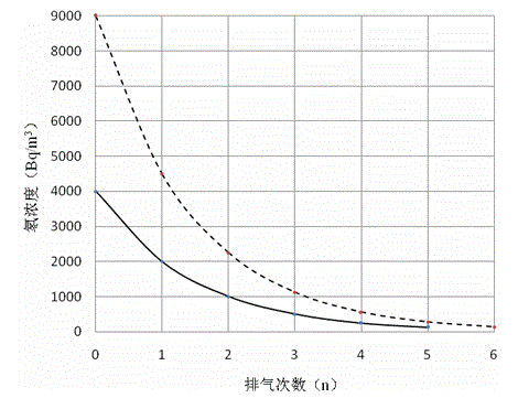
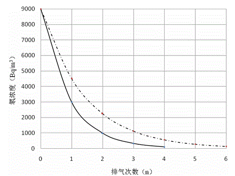
[0025] The radon chamber exhaust gas discharge method provided by the invention will be further described below in conjunction with the accompanying drawings.

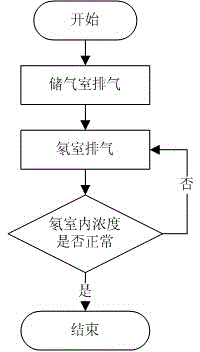
[0026] figure 1 The flow chart of the radon chamber exhaust gas discharge method provided by the present invention is specifically implemented as follows.

[0027] Step ① When the exhaust gas emission from the radon chamber starts, according to the radon concentration C in the radon chamber Rn0 , the radon concentration C that needs to be achieved in the radon room after the discharge Rn1 , single exhaust volume V from the radon chamber to the gas storage chamber RnO , to calculate the required number of discharges n and the exhaust volume V of the gas storage chamber SO , the specific formula is as follows:

[0028] n = log V Rn - V RnO ...


PUM


Abstract

The invention provides a method for discharging waste gas in a radon chamber, and particularly relates to a method for treating the radon waste gas in the radon chamber after instrument calibration is completed in the radon chamber. According to the scheme, after instrument calibration is completed in the radon chamber, the waste gas in the radon chamber is led into another container (gas storage chamber); as the half-life period of radon is 3.82 days, the radon concentration in the gas storage chamber will be lowered after the radon is stored in the gas storage chamber for a period of time; when the radon concentration reaches the concentration stipulated in national discharge stands, the radon in the gas storage chamber is discharged into the atmosphere. According to the method for discharging the waste gas in the radon chamber, the waste gas in the radon chamber can be discharged in a pollution-free mode, and no environmental pollution will be caused while the efficiency of instrument calibration is improved; besides, control in the method is easy and convenient, and automation is easy to implement based on the method.

Description

technical field [0001] The invention relates to a method for discharging waste gas from a radon chamber. Background technique [0002] The radon chamber is used as a standard device for calibrating the radon meter. Researchers are working on how to ensure that the radon concentration, temperature and humidity in the radon chamber remain constant. However, after the radon chamber is calibrated, the radon gas in the radon chamber becomes Exhaust gas needs to be treated to restore the radon concentration in the radon chamber to the normal level before opening the radon chamber and taking out the instruments inside; under normal circumstances, the concentration is dozens or even hundreds of times the ambient concentration. Directly discharge the radon in the radon chamber, which will cause radioactive pollution to the environment around the radon chamber; if the radon in the radon chamber is allowed to decay naturally, it will take a long time, which is not conducive to improvin...

Claims


Application Information

Patent Timeline
IPC IPC(8): G21F9/02B01D53/02
CPCB01D53/02G21F9/02
Inventor 方方余松科丁卫撑张海薇林业李孝哲
Owner CHENGDU UNIVERSITY OF TECHNOLOGY
Learn More