Eureka AIR delivers breakthrough ideas for toughest innovation challenges, trusted by R&D personnel around the world.

Pendular component vibration demonstration instrument

A demonstration instrument and component technology, which is applied in the field of self-excited vibration demonstration and research, and can solve the problems of scarce instruments and unclear mechanism.

Inactive Publication Date: 2015-04-22
南京乐汉东智能设备有限公司 +1
View PDF3 Cites 5 Cited by
  • Summary
  • Abstract
  • Description
  • Claims
  • Application Information

AI Technical Summary

Problems solved by technology

In addition, the current mechanism of self-excited vibration is still unclear, and there are few instruments on the market for self-excited vibration. Therefore, an instrument that can perform quantitative analysis is urgently needed for in-depth research on self-excited vibration.

Method used


Image

  • Pendular component vibration demonstration instrument

Examples


Embodiment Construction

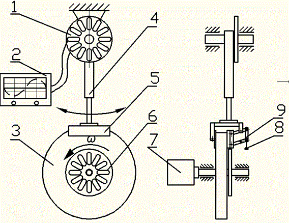
[0011] Such as figure 1 As shown, the compound pendulum mechanism is a structure hinged on the rotating shaft, on which a friction plate 5 is installed; the friction mechanism includes a friction wheel 3 driven by a motor to rotate, and the friction wheel 3 is connected to the friction plate 5 to form a The structure in which the rotating friction wheel 3 drives the swing mechanism 4 to swing by the friction generated by the contacting friction plate.

[0012] The compound pendulum mechanism 4 is equipped with a pressure adjustment mechanism, the pressure adjustment mechanism includes a parallel four-bar linkage mechanism 9, the upper cross bar of the parallel four-bar linkage mechanism 9 is hinged to the compound pendulum mechanism 4, so that the friction plate 5 is adjusted Maintain the parallelism with the friction wheel 3 during pressure; a weight 8 for adjusting the pressure is hung on one end of the parallel four-bar linkage mechanism 9 .

[0013] The pendulum mechanism...


PUM


Abstract

Provided is a pendular component vibration demonstration instrument. A compound pendulum mechanism is of a structure hinged to a spindle and is provided with a friction plate; a friction mechanism comprises a friction wheel, the structure that the compound pendulum mechanism is driven by the rotating friction wheel to swing through friction force generated by the friction wheel and a neighboring friction plate is formed the compound pendulum mechanism is provided with a pressure adjustment mechanism, the moving end of the pressure adjustment mechanism is connected with the friction plate and used for adjusting pressure of the friction plate on the friction wheel, the compound pendulum mechanism is connected with a tilt angle frequency sensor, and the tilt angle frequency sensor is used for detecting tilt angles or the frequency of the compound pendulum mechanism. The pendular component vibration demonstration instrument has the advantage that for a self-induced vibration demonstration and research model, the quantitative research of a self-induced vibration mechanism is achieved by changing rotating speed, the coefficient of friction (change friction plates of different materials and add lubricant oil), and the intrinsic frequency pendulum mechanism is changed.

Description

technical field [0001] The invention relates to the demonstration and research of self-excited vibration, in particular to a vibration demonstrator of a swing member for academic research on friction self-excited vibration and applying the phenomenon and principle of self-excited vibration to the field of daily classroom teaching. Background technique [0002] Self-excited vibration is a unique and common phenomenon. The frictional self-excited vibration model currently demonstrated is basically the friction force generated by the belt drive, which excites the translational degree of freedom vibration of the m-k system. In addition, the current mechanism of self-excited vibration is still unclear, and there are few instruments on the market for self-excited vibration. Therefore, an instrument that can perform quantitative analysis is urgently needed for in-depth research on self-excited vibration. Contents of the invention [0003] The purpose of the present invention is ...

Claims


Application Information

Patent Timeline
Patent Type & Authority Applications(China)
IPC IPC(8): G09B23/10G01H17/00
CPCG09B23/10G01H17/00
Inventor 罗玉军刘建华刘利桁梁洪章潘光陈志张永军
Owner 南京乐汉东智能设备有限公司
Why Eureka
Eureka Blog
Learn More