
Optical fringes automatic counting device and counting method based on optical fiber

An automatic counting and optical fiber technology, applied in the field of optical detection, can solve the problems of slow manual counting speed, limited experiment progress, and many counts, and achieve the effects of convenient movement and operation, improved sensitivity, and flexible and simple measurement

Inactive Publication Date: 2015-04-22
SHANDONG NORMAL UNIV
View PDF9 Cites 2 Cited by
  • Summary
  • Abstract
  • Description
  • Claims
  • Application Information

AI Technical Summary

Problems solved by technology

[0006] (1) Due to the large number of counts, it is easy to cause counting errors;
[0007] (2) The manual counting speed is slow, which seriously limits the progress of the experiment;
[0008] (3) Due to the weak brightness of the stripes, counting for a long time is easy to cause eye fatigue
[0010] (1) Photodiodes are used to collect stripes. When the stripes are thin, especially when the stripe size is smaller than the photodiode lighting area, it is difficult to achieve accurate counting
[0011] (2) Although the linear array CCD has high counting accuracy, the device is complicated and the cost is high

Method used


Image

  • Optical fringes automatic counting device and counting method based on optical fiber
  • Optical fringes automatic counting device and counting method based on optical fiber
  • Optical fringes automatic counting device and counting method based on optical fiber

Examples


Embodiment Construction

[0033] The present invention is described in detail below in conjunction with accompanying drawing:

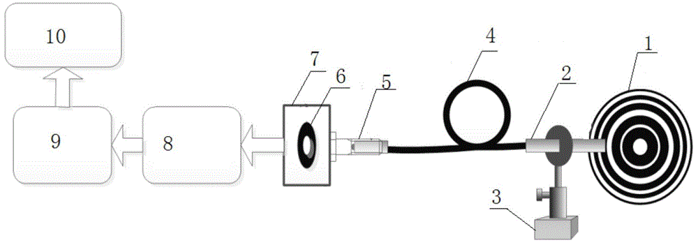
[0034] The design schematic diagram of optical fringe automatic counting device based on optical fiber is attached figure 1 shown.

[0035] (1) The fiber optic probe 2 is designed with an SMA905 connector. The fiber core diameter of the fiber 4 is 200um.

[0036] (2) Fix the fiber probe 2 vertically at 1 mm in front of the light screen with the fiber clamp 3 .

[0037] (3) The length of the optical fiber 4 is 50 cm, and it is connected to the light-shielding cavity 7 through a standard SMA905 connector.

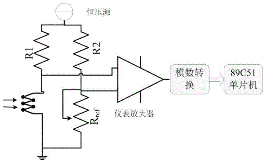
[0038] (4) The light-shielding cavity 7 is processed by an aluminum shell and blackened, and the photodetector 6 is a photoresistor. The photodetector 6 converts the light and dark signals collected by the optical fiber probe 2 into corresponding electrical signals, and the microprocessor 9 collects and judges the state of the light and dark stripes through the signal coll...


PUM


Abstract

The invention discloses an optical fringes automatic counting device and counting method based on optical fiber including a fiber-optics probe adopting a standard SMA contact package, fiber-optics probe connecting with a optical fiber connector through optical fiber, the optical fiber connector connecting with a photoelectric detector, collected light and shade signals being converted to electrical signals by the photoelectric detector, light and shade fringe state judged and counted by a microprocessor through a signal acquisition circuit, measuring results displaying on the display unit by the microprocessor in real time. The optical fringes automatic counting device and counting method based on optical fiber adopts optical fiber serving as a light and shade fringe collecting prob. Since daylighting area of the optical fiber is far smaller than the size of the light and shade fringe, detective sensitivity can be improved greatly according to a verified embodiment. In addition, because the fiber-optics probe can be convenient to move and to operate, measurement is more flexible, simple and convenient.

Description

technical field [0001] The invention relates to the field of optical detection, in particular to an optical fiber-based automatic counting device and a counting method for optical stripes. Background technique [0002] Optical interference and diffraction measurement technology plays an important role in the field of optical detection. It is not only widely used in actual production and life, but also has great significance in optical teaching and scientific research in colleges and universities, such as Newton rings, Michelson interference, small hole diffraction and other experimental projects. . Taking the Michelson interference experiment as an example, the formula for measuring the wavelength of monochromatic light is: [0003] λ = 2 × Δd N [0004] Among them, N is the number of fringes produced or disappeared by the Michelson interferometer, and Δd is the scale difference on the re...

Claims


Application Information

Patent Timeline
Patent Type & Authority Applications(China)
IPC IPC(8): G06M1/272
Inventor 岳伟伟
Owner SHANDONG NORMAL UNIV
Learn More