
A temperature difference control structure for energy-saving kilns

A technology of temperature difference control and kiln, applied in the direction of furnace, furnace type, lighting and heating equipment, etc., can solve problems such as cracking, waste products, product deformation, etc.

Active Publication Date: 2017-06-13
MODENA TECH LTD
View PDF5 Cites 0 Cited by
  • Summary
  • Abstract
  • Description
  • Claims
  • Application Information

AI Technical Summary

Problems solved by technology

However, due to the widening of the kiln section, there will be temperature differences due to insufficient flame range, resulting in product deformation and cracking, resulting in waste products

Method used


Image

  • A temperature difference control structure for energy-saving kilns
  • A temperature difference control structure for energy-saving kilns

Examples


Embodiment Construction

[0009] The present invention will be further described below in conjunction with specific embodiment:

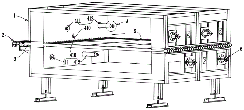
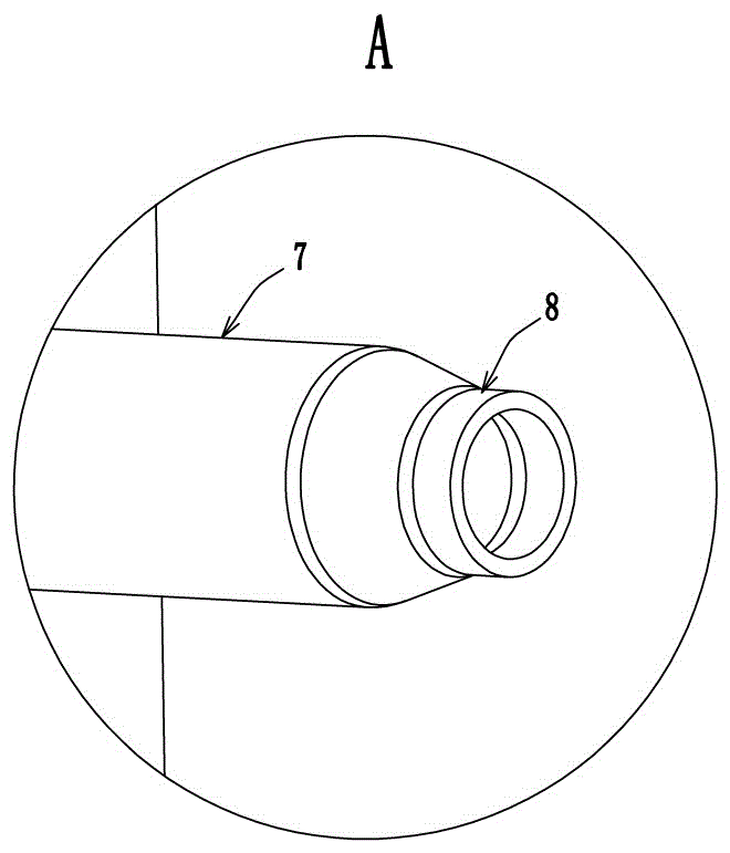
[0010] See attached figure 1 As shown, a temperature difference control structure for firing equipment described in this embodiment, the new temperature difference control structure includes a kiln frame 1, a roller conveying assembly 3 installed on the kiln frame 1, for driving The transmission mechanism 2 for the rotation of the roller conveying assembly 3, multiple sets of combustion splitter assemblies 4 symmetrically installed on both sides of the kiln frame and arranged along the conveying direction of the roller conveying assembly 3, and used to provide the combustion splitter assembly 4 Burner 6 for heat. Each set of combustion splitter assembly 4 includes a pair of combustion splitter groups 410 respectively installed on the upper and lower sides of the roller conveying assembly 3, wherein each combustion splitter group 410 also includes a combustion divider group...


PUM


Abstract

The invention provides a novel temperature difference control structure that can reduce the temperature difference in the direction of the wide section in the kiln and effectively prevent product deformation or cracking during ceramic sintering. The transmission mechanism for the rotation of the conveying assembly also includes multiple sets of combustion splitter assemblies arranged symmetrically on both sides of the frame along the conveying direction of the roller bar conveying assembly and burners for providing heat to the combustion splitter assembly; ceramic products are sintered When forming, because the above-mentioned structure adopts the structure of long and short combustion splitters, the flame of the long combustion splitter is close to the middle, and the flame of the short combustion splitter is close to the side wall, so that the ceramic products in the kiln are heated along the direction of its wide section. It is basically consistent, thereby improving the uneven heating environment of the traditional ceramic products located in the middle of the kiln during sintering, and effectively reducing the deformation or cracking of ceramic products due to temperature differences during sintering.

Description

technical field [0001] The invention relates to the technical field of firing equipment for ceramic products, in particular to a temperature difference control structure for an energy-saving kiln. Background technique [0002] During the sintering and molding process of ceramic products in the existing roller kiln or tunnel kiln, it is mainly fired at high temperature through the combustion splitters arranged on the side walls of both sides of the kiln. However, due to the widening of the cross-section of the kiln, there will be temperature differences due to insufficient flame range, resulting in product deformation and cracking, resulting in waste products. Contents of the invention [0003] The purpose of the present invention is to overcome the deficiencies of the prior art and provide a temperature difference control structure for firing equipment that can reduce the temperature difference in the direction of the wide section in the kiln and effectively prevent produc...

Claims


Application Information

Patent Timeline
Patent Type & Authority Patents(China)
IPC IPC(8): F27B9/40F27B9/36
Inventor 管火金陶志坚程希如郑旭东陆志佳吴家威
Owner MODENA TECH LTD
Learn More