Fuel gas inlet branch pipe sealing structure for double-fuel engine

A dual-fuel engine and gas intake technology, applied to the sealing device of the engine, combustion engine, internal combustion piston engine, etc., can solve the problems of safety accidents, leakage, safety hazards, etc., to prevent gas leakage, improve safety, and reliability sealing effect

Inactive Publication Date: 2015-04-22
CHONGQING PUSH MECHANISM
View PDF0 Cites 5 Cited by
  • Summary
  • Abstract
  • Description
  • Claims
  • Application Information

AI Technical Summary

Problems solved by technology

[0003] High-power dual-fuel engines generally adopt the multi-point injection intake method, which ensures the best mixing ratio of natural gas and diesel under different working conditions, and greatly improves the economy of the engine. However, gas leakage is prone to occur during the transmission process in the engine , which in turn creates potential safety hazards, especially at the connection between the gas intake branch pipe and the gas injection valve. Since it is relatively close to the engine combustion chamber, once a leak occurs, it is very easy to cause a safety accident. Therefore, reliable sealing of the connection is particularly important.

Method used


Image

  • Fuel gas inlet branch pipe sealing structure for double-fuel engine
  • Fuel gas inlet branch pipe sealing structure for double-fuel engine
  • Fuel gas inlet branch pipe sealing structure for double-fuel engine

Examples


Embodiment Construction

[0019] The present invention will be further described below in conjunction with embodiment and accompanying drawing.

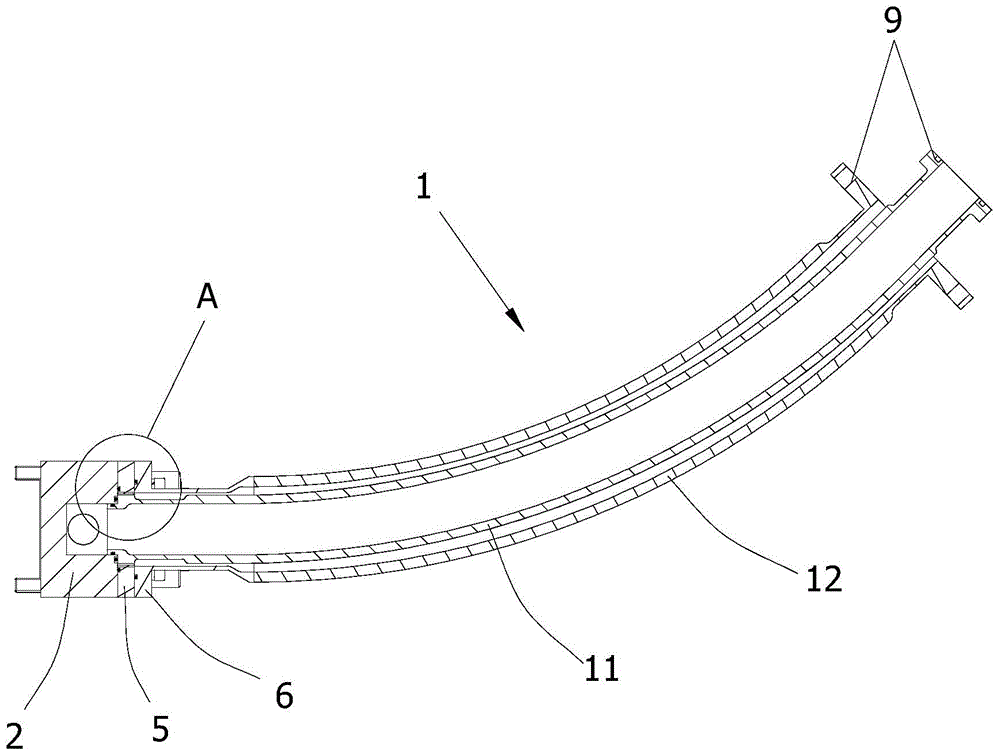
[0020] Such as figure 1 The sealing structure of a gas intake branch pipe of a dual-fuel engine shown includes a gas intake branch pipe 1 and a gas injection valve 2. The gas intake branch pipe 1 and the gas injection valve 2 are connected by a flange. The gas intake branch pipe 1 It is a double-layer structure, including an inner pipe 11 and an outer pipe 12. The inner pipe 11 is penetrated in the outer pipe 12. The length of the inner pipe 11 is longer than that of the outer pipe 12. One end of the inner pipe 11 and the end of the outer pipe 12 are respectively fixed with end face flanges 9 to facilitate the connection of the gas inlet main pipe (not shown in the figure).

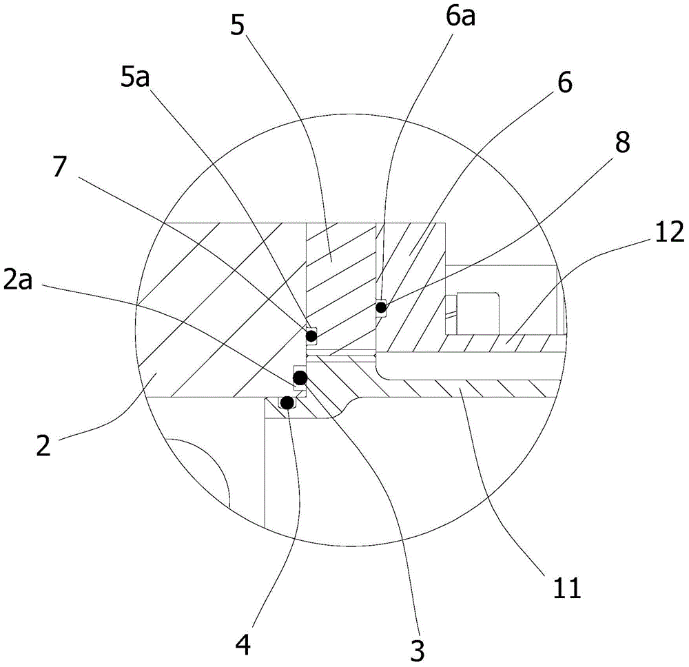
[0021] See image 3 , at one end connected to the gas injection valve 2, the inner pipe 11 protrudes from the end surface of the outer pipe 12, and on its protruding end is provided wi...


PUM


Abstract

The invention discloses a fuel gas inlet branch pipe sealing structure for a double-fuel engine. The fuel gas inlet branch pipe sealing structure for the double-fuel engine comprises a fuel gas inlet branch pipe and a fuel gas injection valve connected with one end of the fuel gas inlet branch pipe. The fuel gas inlet branch pipe is of a double-layer structure and comprises an inner pipe body and an outer pipe body, the end, connected with the fuel gas injection valve, of the inner pipe body extends out of the end face of the outer pipe body, and the extension end of the inner pipe body is provided with a protruding portion and an extending portion, wherein the protruding portion extends outwards in the radial direction, and the extending portion extends into the fuel gas injection valve in the length direction. A first end face O-shaped seal ring is arranged between the end face of the protruding portion and the end face of the fuel gas injection valve. The outer wall of the protruding portion is in abutting joint with the inner wall of the fuel gas injection valve, and a radial O-shaped seal ring is arranged between the outer wall of the protruding portion and the inner wall of the fuel gas injection valve. The fuel gas inlet branch pipe sealing structure for the double-fuel engine is simple and novel in structure and capable of guaranteeing reliable sealing of the connection portion between the fuel gas inlet branch pipe and the fuel gas injection valve and preventing fuel gas leakage, and improves the safety of the double-fuel engine.

Description

technical field [0001] The invention belongs to the technical field of engines, and relates to a sealing structure of a gas intake branch pipe of a dual-fuel engine. Background technique [0002] The International Maritime Organization (IMO) has increasingly stringent emission requirements, and some regions have clearly required that the emission in 2016 should reach Tier III. In order to meet this requirement, it is necessary not only to optimize the design of the engine structure, but also to use cleaner and more environmentally friendly new fuel. As a clean energy, natural gas has been widely used in the automotive field at home and abroad, and has played a significant role in reducing engine emissions. In terms of high-power engines, dual-fuel engines using liquefied natural gas (LNG) + diesel (MDO) or compressed natural gas (CNG) + diesel (MDO) as the main fuel have also been developed. [0003] High-power dual-fuel engines generally adopt the multi-point injection in...

Claims


Application Information

Patent Timeline
IPC IPC(8): F02M21/02F02F11/00
CPCY02T10/30
Inventor 田华清
Owner CHONGQING PUSH MECHANISM
Why Eureka
Try Eureka