
Device for cleaning a spray gun

A technology of equipment and spray gun, which is applied in the equipment field of cleaning spray gun, and can solve the problem that the cleaning equipment cannot be reliably positioned

Inactive Publication Date: 2015-04-15
FILLON PICHON SOCIETE ANONYME
View PDF4 Cites 3 Cited by
  • Summary
  • Abstract
  • Description
  • Claims
  • Application Information

AI Technical Summary

Problems solved by technology

[0007] However, it has been observed that other types of guns cannot be reliably positioned in this cleaning device known from the prior art

Method used


Image

  • Device for cleaning a spray gun
  • Device for cleaning a spray gun
  • Device for cleaning a spray gun

Examples


Embodiment Construction

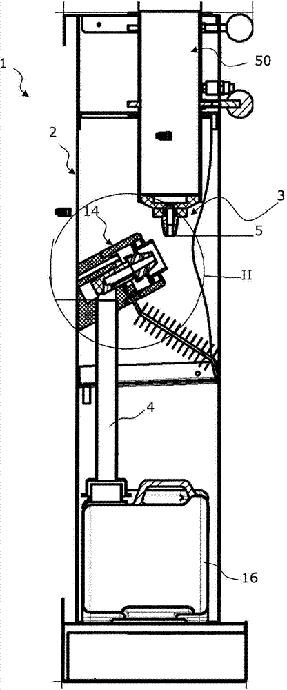
[0036] As indicated above, the cleaning device 1 of the present invention has a support structure 2 defining a cleaning volume, such as an enclosure, adapted to at least partially receive a spray gun 26 to be cleaned.

[0037] Specifically, the spray gun 26 is provided with a fluid inlet 27 for receiving the fluid to be sprayed and is provided with a fluid outlet 29, which is called "paint inlet" 27 and has an axis indicated by A27, and which is called "paint outlet". , the fluid outlet has an axis indicated at A29. An internal conduit connects the paint inlet 27 of the gun 26 to the paint outlet 29 .

[0038]Such guns are also provided with a gas inlet 31 which can be connected to a gas feed source such as a compressed air feed source. In particular, this air inlet 31 makes it possible to facilitate the flow of paint from the paint inlet 27 to the fluid outlet 29 and, when the trigger of the gun is actuated, to facilitate the ejection of paint from said gun. Said air inlet ...


PUM


Abstract

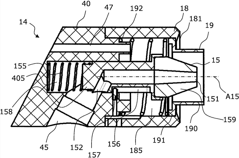
The invention concerns a cleaning device for a gun having a fluid inlet, an outlet for said fluid, a gas inlet and an outlet for said gas. Said cleaning device comprises a support frame, a fluid supply head carried by said frame and connectable to said paint inlet of the gun, and a system (14) for receiving fluid which comprises a receiving nozzle (15) having a fluid channel (150) of which the inlet (151) can be connected with the fluid spray outlet (29) of the gun, and a gas discharge pipe (47) of which the inlet can be connected with the gas outlet of said gun. Said nozzle (15) is mounted movable relative to the frame, in a direction parallel to the axis of the inlet (151) of the fluid channel (150) of the receiving nozzle (15), between a close position of the supply head (3) and a separated position of said supply head (3).

Description

technical field [0001] The present invention generally relates to an apparatus for cleaning a spray gun. [0002] More specifically, the present invention relates to an apparatus for cleaning a spray gun having a fluid inlet for a fluid to be sprayed, a fluid outlet for said fluid to be sprayed, a gas inlet for pressurized gas and a The gas outlet for the pressurized gas, the fluid inlet is called "paint inlet". The cleaning apparatus includes: a support structure; a fluid feed head supported by the structure and connectable to the paint inlet of a gun; and a fluid and gas receiving system. The fluid and gas receiving system comprises firstly a fluid receiving nozzle and secondly a gas removal conduit, the fluid receiving nozzle having a fluid channel connectable at its inlet to a fluid outlet of the gun for the fluid to be sprayed, and The fluid channel is connected at its outlet to collecting means for collecting the ejected fluid, and the gas removal conduit is connectabl...

Claims


Application Information

Patent Timeline
IPC IPC(8): B08B3/00B08B9/032B05B7/24B05B15/02B05B15/12B44D3/00B65D83/38B05B14/00B05B15/55
CPCB08B9/0321B08B3/006B05B15/0266B44D3/006B05B15/557B05B14/00B05B15/55B05B14/49
Inventor 帕特里克·桑特
Owner FILLON PICHON SOCIETE ANONYME
Learn More