
Patterned photoresist layer forming method and wafer-stage chip packaging method

A technology of photoresist layer and packaging method, which is applied in the field of semiconductors, can solve the problems of simplifying the manufacturing process, reducing manufacturing costs, disadvantages, etc., and achieve the effects of simplifying the manufacturing process, simple forming process, and reducing manufacturing costs

Inactive Publication Date: 2015-04-15
SEMICON MFG INT (SHANGHAI) CORP
View PDF7 Cites 7 Cited by
  • Summary
  • Abstract
  • Description
  • Claims
  • Application Information

AI Technical Summary

Problems solved by technology

[0012] Another problem to be solved by the present invention is: in the existing wafer-level chip packaging method based on through-silicon via technology, the price of the dry film used to form rewiring is very expensive, and the formation process of the dry film is very complicated, which is not conducive to Reduce manufacturing cost and simplify manufacturing process

Method used


Image

  • Patterned photoresist layer forming method and wafer-stage chip packaging method
  • Patterned photoresist layer forming method and wafer-stage chip packaging method
  • Patterned photoresist layer forming method and wafer-stage chip packaging method

Examples


Embodiment Construction

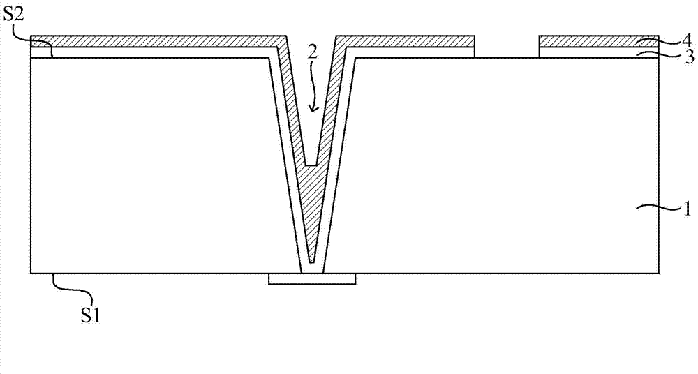
[0048] After research, it is found that in the existing wafer-level chip packaging method based on through-silicon via technology, the reason why the patterned photoresist layer located in the through-hole is difficult to remove is:

[0049] like figure 2 As shown, the patterned photoresist layer 4 is made by a photolithography process using a photoresist with the same viscosity and a high viscosity. The photolithography process includes: a glue coating step, a soft baking step after glue coating 1. An exposure step after soft baking, due to the high viscosity of the patterned photoresist layer 4, will bring the following effects: 1) the viscosity of the patterned photoresist layer 4 and the viscosity of the patterned photoresist layer 4 In direct proportion, the thickness of the patterned photoresist layer 4 is uneven, especially the patterned photoresist layer 4 filled at the bottom of the through hole 2 is relatively thick; 2) the patterned photoresist layer 4 has strong a...


PUM

PropertyMeasurementUnit
Thicknessaaaaaaaaaa
Thicknessaaaaaaaaaa

Abstract

A patterned photoresist layer forming method and a wafer-stage chip packaging method are disclosed. The wafer-stage chip packaging method comprises following steps: (1) during manufacturing of a patterned photoresist layer used for forming a re-wire arrangement, coating a substrate with a first photoresist layer in a first viscosity being less than 100cp so that the first photoresist layer is a low-viscosity photoresist layer; (2) coating the first photoresist layer with a second photoresist layer in a second viscosity being higher than the first viscosity; and (3) performing exposure and development to the first photoresist layer and the second photoresist layer. Because that adhesivity of the low-viscosity photoresist layer is weaker than that of the high-viscosity photoresist layer, the patterned photoresist layer, compared with a patterned photoresist layer in the prior art, is easier to remove, so that residue of the patterned photoresist layer in through holes is avoided.

Description

technical field [0001] The invention relates to the technical field of semiconductors, in particular to a method for forming a patterned photoresist layer and a wafer-level chip packaging method based on through-silicon via technology. Background technique [0002] Through Silicon Via (TSV for short) technology is an interconnection technology that realizes circuit conduction between chips, between wafers, or between wafers. Unlike previous IC package bonding and overlay technologies using bumps, through-silicon via technology enables chips to be stacked in the three-dimensional direction with the highest density and the smallest size. [0003] An existing wafer-level chip packaging method based on through-silicon via technology includes: [0004] like figure 1 As shown, a wafer 1 is provided, and the wafer 1 has a front side S1 and a back side S2, wherein a circuit structure is formed on the front side S1 of the wafer 1, and a through hole 2 with a large aspect ratio is f...

Claims


Application Information

Patent Timeline
IPC IPC(8): G03F7/00H01L21/3105H01L21/768
Inventor 陈福成
Owner SEMICON MFG INT (SHANGHAI) CORP
Learn More