
Engine

A technology of engine and connecting rod, which is applied in the direction of engine components, machines/engines, mechanical equipment, etc., which can solve the problems such as the unsmooth movement of the connecting rod and piston, and achieve the effect of smooth movement

Inactive Publication Date: 2015-04-15
YAMAHA MOTOR POWER PROD KK
View PDF6 Cites 4 Cited by
  • Summary
  • Abstract
  • Description
  • Claims
  • Application Information

AI Technical Summary

Problems solved by technology

[0004] In this type of engine, although the surroundings of the intake and exhaust valves in the valve chamber can be lubricated with oil, the pin hole of the pin boss, the inner surface of the small end of the connecting rod, and the outer periphery of the piston pin cannot be sufficiently lubricated. Around the back of the piston
Therefore, the movement of the connecting rod relative to the piston may not be smooth
In particular, when the bearing shell fitted into the small end of the existing connecting rod is omitted, this problem becomes remarkable.

Method used


Image

  • Engine
  • Engine
  • Engine

Examples


Embodiment Construction

[0021] Hereinafter, embodiments of the present invention will be described with reference to the drawings.

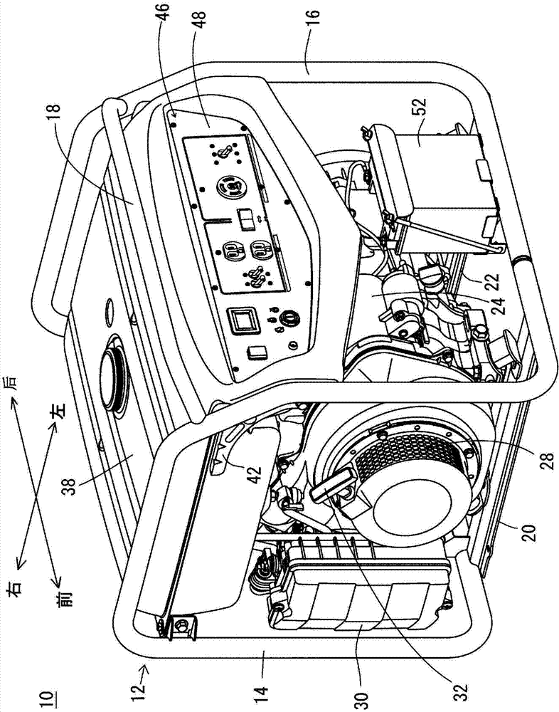
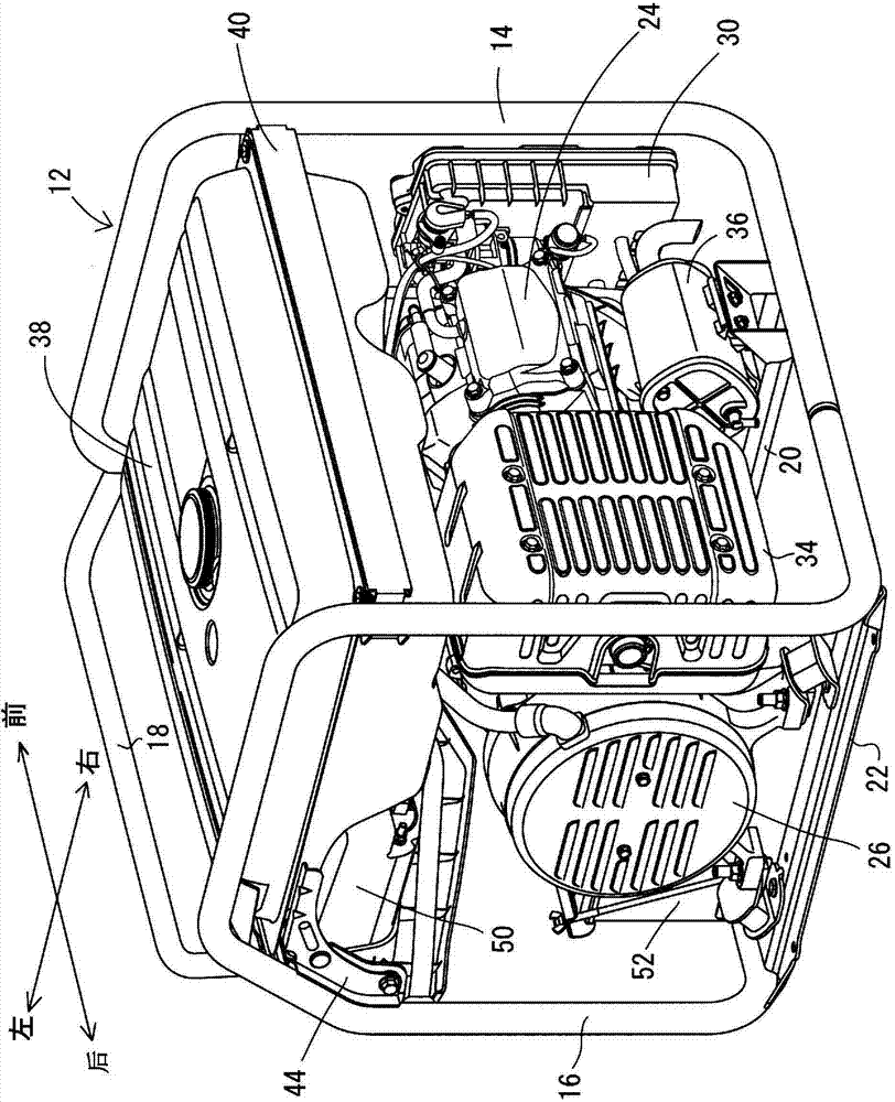
[0022] figure 1 with figure 2 An engine generator 10 including an engine 24 (described later) according to one embodiment of the present invention is shown. In this specification, for the convenience of description, in the engine generator 10, such as figure 1 with figure 2 As shown, define "front-back direction" and "left-right direction". Therefore, the side where the engine 24 is installed is "front", the side where the generator 26 (described later) is installed is "rear", and the side where the operation panel 48 (described later) is installed is "left".

[0023] The engine generator 10 is a portable generator and includes a generator frame (frame) 12 . The generator frame 12 includes a front frame 14 , a rear frame 16 , an upper frame 18 , and a pair of lower frames 20 , 22 . The front frame 14 is formed in a tubular shape and is generally in an inverted U...


PUM


Abstract

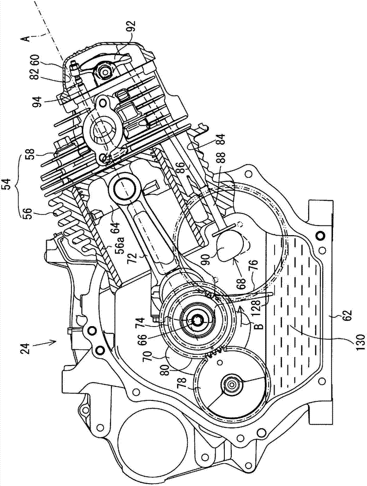
An engine includes a piston inside a cylinder, a crank shaft, a connecting rod, an oil dipper provided in a big end portion of the connecting rod, and a piston pin which connects pin boss regions of the piston to a small end portion of the connecting rod, and a crank case. The piston pin is rotatably movable with respect to the pin boss regions and the connecting rod. There are counter regions between the small end portion and the piston pin, a first counter region on a side closer to a tip portion of the connecting rod and a second counter region on a side closer to the big end portion of the connecting rod. The first counter region includes two ends located farther inward than two ends of the second counter region in an axial direction of the piston pin.

Description

technical field [0001] The present invention relates to engines, and in particular to OHV engines subjected to oil splash lubrication. Background technique [0002] An example of such prior art is disclosed in Japanese Patent Application Laid-Open No. 2004-218488. [0003] The engine disclosed in Japanese Patent Application Laid-Open No. 2004-218488 is an air-cooled single-cylinder four-stroke OHV engine, and oil stored at the bottom of the crankcase is splashed by a splash portion formed at the large end of the connecting rod. The splashed oil and oil mist including mist oil components are supplied to the surroundings of the intake and exhaust valves in the valve chamber through the oil supply passage. As a result, the vicinity of the intake and exhaust valves can be lubricated without using an oil pump. [0004] In this type of engine, although the surroundings of the intake and exhaust valves in the valve chamber can be lubricated with oil, the pin hole of the pin boss,...

Claims


Application Information

Patent Timeline
Patent Type & Authority Applications(China)
IPC IPC(8): F01M9/06
CPCF02F7/0004F01M9/06F02F3/0069F02F3/0084F16C7/023F02B63/04F16J1/16F16J1/08
Inventor 铃木笃
Owner YAMAHA MOTOR POWER PROD KK
Learn More