
A flexible combined welding assembly line

A welding assembly line and flexible technology, applied in the direction of welding equipment, auxiliary welding equipment, welding/cutting auxiliary equipment, etc., can solve the problems of lower welding production efficiency, high manufacturing cost, and narrow application range, so as to reduce equipment investment cost, The effect of reducing production cost and improving production efficiency

Inactive Publication Date: 2016-03-30
JIANGSU UNIV OF SCI & TECH IND TECH RES INST OF ZHANGJIAGANG +1
View PDF6 Cites 0 Cited by
  • Summary
  • Abstract
  • Description
  • Claims
  • Application Information

AI Technical Summary

Problems solved by technology

[0002] At present, traditional robot welding mostly adopts the form of a workstation, that is, one or several robots form a workstation, and the workstation exists independently of each other as an isolated processing unit. The disadvantages are: 1. Due to the limitation of the working range of the robot, the workstation 2. The position and quantity of the positioner in the workstation are fixed and cannot be rearranged according to the processing requirements, so the scope of application is narrow; 3. For some welding requirements are high and processing is difficult Larger parts may need to be repositioned multiple times in the production process to meet the requirements. It needs to be equipped with an expensive multi-dimensional positioner. The manufacturing cost is high, and multiple displacements will reduce the efficiency of welding production

Method used


Image

  • A flexible combined welding assembly line
  • A flexible combined welding assembly line
  • A flexible combined welding assembly line

Examples


Embodiment Construction

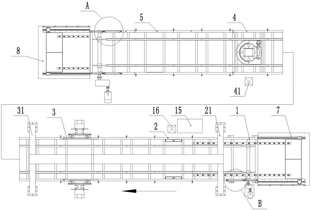
[0049] The specific implementation of the present invention will be described in detail below in conjunction with the accompanying drawings, taking a flexible combined welding line with a non-displacement welding device, a flip welding device, and a rotary welding device in sequence as an example.

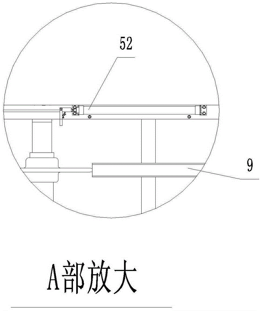
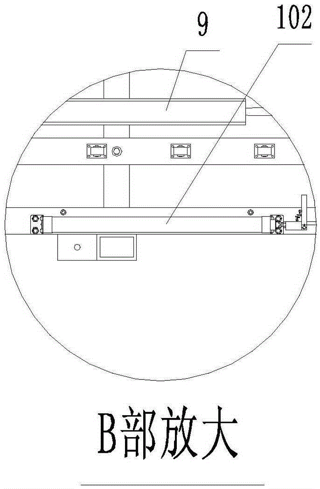
[0050] Such as Figure 1-3 As shown, a flexible combined welding line includes a conveying mechanism and five pallets 6 running in the conveying mechanism for clamping workpieces. The conveying mechanism includes a head-end module 1, three middle modules, and a tail-end module 5 that are detachably connected together, and two parallel forward conveying chains 9 that run through all the modules and two forward conveying chains 9 below. The return conveyor chain 10 arranged side by side. Positioning guide plates are respectively provided on both sides of the accompanying fixture 6 on the frame of the head end module 1 and the middle module. The conveying mechanism also includes a f...


PUM


Abstract

The invention discloses a flexible combined welding assembly line which can be used for welding all directions of a workpiece and randomly increasing or deleting a welding station according to production requirements, and has a simple structure and low manufacturing cost. The flexible combined welding assembly line comprises a conveying mechanism and a plurality of follow fixtures which are operated in the conveying mechanism and are used for clamping the workpiece; the conveying mechanism comprises a front end module, a plurality of middle modules and a tail end module which are detachably connected together, two forward direction conveying chains which penetrate through all the modules and are arranged in parallel, and two returning conveying chains which are located under the two forward direction conveying chains and are arranged in parallel; the conveying mechanism is provided with one or more of a deflection-free welding device, an overturning welding device and a rotary welding device according to welding production requirements; one or more welding devices with each type can be arranged according to the production requirements.

Description

technical field [0001] The invention relates to a welding device, in particular to a flexible combined welding line. Background technique [0002] At present, traditional robot welding mostly adopts the form of a workstation, that is, one or several robots form a workstation, and the workstation exists independently of each other as an isolated processing unit. The disadvantages are: 1. Due to the limitation of the working range of the robot, the workstation 2. The position and quantity of the positioner in the workstation are fixed and cannot be rearranged according to the processing requirements, so the scope of application is narrow; 3. For some welding requirements are high and processing is difficult Larger parts may need to be repositioned multiple times in the production process to meet the requirements. It needs to be equipped with an expensive multi-dimensional positioner. The manufacturing cost is high, and multiple displacements will reduce the efficiency of weldi...

Claims


Application Information

Patent Timeline
Patent Type & Authority Patents(China)
IPC IPC(8): B23K37/00B23K37/04B23K37/047
CPCB23K37/00B23K37/04B23K37/047
Inventor 唐文献杨栋张玉飞张建秦文龙夏小帅李钦奉苏世杰
Owner JIANGSU UNIV OF SCI & TECH IND TECH RES INST OF ZHANGJIAGANG
Learn More