
Extended operating cycle for pressurized water reactor

A technology of pressurized water reactors and nuclear reactors, applied in the direction of reactors, nuclear reactors, overall reactors, etc.

Inactive Publication Date: 2015-04-08
BABCOCK & WILCOX MPOWER
View PDF8 Cites 3 Cited by
  • Summary
  • Abstract
  • Description
  • Claims
  • Application Information

AI Technical Summary

Problems solved by technology

However, reordering is highly labor intensive and the reactor must be shut down each time a reordering operation is performed

Method used


Image

  • Extended operating cycle for pressurized water reactor
  • Extended operating cycle for pressurized water reactor
  • Extended operating cycle for pressurized water reactor

Examples


Embodiment Construction

[0021] Detailed description of preferred embodiments

[0022] This paper discloses an improved fuel cycle management technology for pressurized water reactors (PWR), which can extend the operation cycle without using soluble poisons such as soluble boron for reaction rate control, and optionally without fuel Component rearrangement.

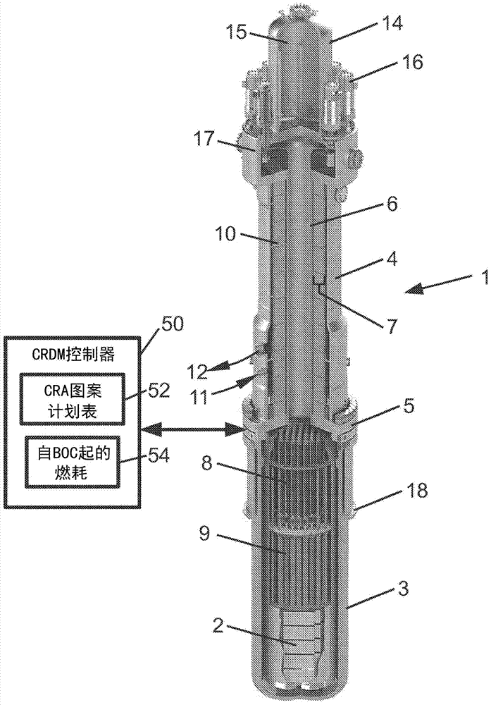
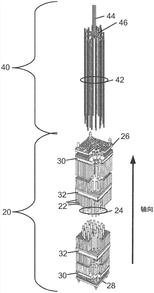
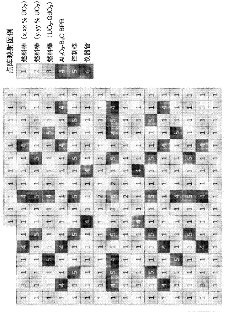
[0023] reference figure 1 , Shows an illustrative small modular reactor (SMR) 1, with which the reaction rate control technology disclosed herein can be suitably adopted. Illustrative SMR 1 is a type of pressurized water reactor (PWR). The illustrative PWR 1 includes a nuclear reactor core 2 disposed in a pressure vessel, which in the illustrative embodiment includes a lower vessel portion 3 and an upper vessel portion 4 connected by a middle flange 5. The reactor core 2 is arranged in the lower vessel part 3 and includes fissionable materials immersed in the main cooling water (such as: 235 U). A cylindrical central riser 6 is coaxially arranged i...


PUM


Abstract

A pressurized water reactor (PWR) includes a pressure vessel containing a nuclear reactor core immersed in primary coolant water, control rod assemblies (CRA's), and control rod drive mechanisms (CRDM's) operating the CRA's. The reactor core has axially varying 235U enrichment and / or axially varying burnable poison concentration. A CRDM controller controls the CRA's over a burn-up cycle that does not include fuel assembly shuffling and is divided into a plurality of burn-up intervals. The CRDM controller is configured to, for each burn up interval: position the CRA's in accordance with a CRA pattern defining a set of fixed positions for the CRA's except for a sub-set of CRA's designated by the CRA pattern as floating CRA's, and control power level of the PWR by adjusting the floating CRA's without not adjusting the CRA's not designated as floating CRA's. The primary coolant water optionally does not contain soluble neutron poison.

Description

[0001] This application claims the rights of U.S. Provisional Application No. 61 / 625,152 filed on April 17, 2012. U.S. Provisional Application No. 61 / 625,152 filed on April 17, 2012 is incorporated herein by reference in its entirety. Background technique [0002] The following involves nuclear reactor technology, nuclear reactor operation technology, nuclear power generation technology and related technologies. [0003] In nuclear power plants, fissionable materials (usually based on 235 U's) are consumables with high-cost components. Therefore, it is desirable to maximize the utilization of nuclear fuel (sometimes referred to as "burnup") during the fuel cycle that extends from the beginning of the cycle of nuclear fuel (BOC) to the end of cycle (EOC). [0004] In a typical arrangement, a single fuel assembly includes an array or grid of fuel rods containing fissionable material. The fuel assembly further includes a diffused pipe in which a control rod including a neutron absorbi...

Claims


Application Information

Patent Timeline
Patent Type & Authority Applications(China)
IPC IPC(8): G21C3/326G21C7/04G21C7/117
CPCG21C2003/3262Y02E30/32G21C7/00G21C7/04G21C1/322Y02E30/38G21C5/18G21C7/08Y02E30/39G21C3/326G21C3/3262G21D3/08Y02E30/30Y02E30/00
Inventor V·J·彼洛弗斯基
Owner BABCOCK & WILCOX MPOWER
Learn More