Gap measurement device for combustor, and gap measurement method

A technology of measuring device and measuring method, applied in combustion method, measuring device, gas turbine device, etc., can solve the problem that there is no size measuring device capable of measuring the annular gap between the cyclone support cylinder and the combustion cylinder, and the cyclone support cannot be measured. The annular gap between the cylinder and the combustion cylinder can be solved to achieve the effect of reliable shooting.

Inactive Publication Date: 2015-04-08
MITSUBISHI POWER LTD
View PDF5 Cites 0 Cited by
  • Summary
  • Abstract
  • Description
  • Claims
  • Application Information

AI Technical Summary

Problems solved by technology

[0012] However, at present, when assembling the combustor, after assembling the combustion tube and the like into the vehicle compartment, the swirler support tube is installed in the vehicle compartment together with the nozzle assembly. And after the swirler support cylinder is installed in the vehicle compartment, the annular gap between the cyclone support cylinder and the combustion cylinder cannot be measured
[0013] On the other hand, in the state where the swirler support cylinder, the combustion cylinder, etc. are assembled and the burner is assembled, there is no measuring device capable of measuring the size of the annular gap between the swirler support cylinder and the combustion cylinder.
[0014] For example, in Patent Documents 1 and 2, there is no description of the measuring device and measuring method for measuring the size of the annular gap between the swirler support cylinder and the combustion cylinder.

Method used


Image

  • Gap measurement device for combustor, and gap measurement method
  • Gap measurement device for combustor, and gap measurement method
  • Gap measurement device for combustor, and gap measurement method

Examples


Embodiment Construction

[0066] Hereinafter, embodiments of the present invention will be described in detail based on the drawings. However, the scope of the present invention is not limited to the following embodiments. The dimensions, materials, shapes, relative arrangements, and the like of components described in the following embodiments are not intended to limit the scope of the present invention thereto, but are merely illustrative examples. In the following embodiments, a case where it is applied to a combustor constituting a gas turbine will be described.

[0067]

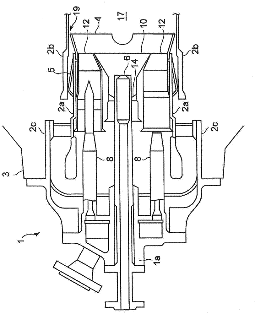
[0068] figure 1 It is a sectional view showing the structure of the combustor according to the embodiment of the present invention.

[0069] Such as figure 1 As shown, the combustor 1 is equipped with: a swirler support cylinder 2a (equivalent to the first cylinder, sometimes called an inner cylinder) provided on the fuel supply side; Combustion cylinder 2b (corresponding to the second cylinder body; sometimes referred to a...


PUM


Abstract

The purpose of the present invention is to provide a gap measurement device (20) for a combustor (1) and a gap measurement method, with which the size of a gap between a first cylindrical body (2a) surrounding the periphery of a combustion nozzle, and a second cylindrical body (2b) which is connected to the first cylindrical body (2a) and which guides combustion gas to a down-stream side, can be measured when the combustor (1) is in an assembled state. This gap measurement device (20) for the combustor (1) is provided with: a rod member (30) which, in a state of being inserted inside the combustor (1), is attached to a first flange (1a) of the combustor (1), at least a base-end side of said rod member (30) being hollow; a support member (50) attached to a tip of the rod member (30) so as to be capable of rotating about a shaft core (55) orthogonal to the axial direction of the rod member (30); an imaging element (60) which is supported on the support member (50), and which images an annular gap (19); an operation lever (70) which passes through the inside of the rod member (30), and which extends towards the support member (50); and a link mechanism (80) which is provided between the operation lever (70) and the support member (50), and which converts back-and-forth movement of the operation lever (70) into rotational movement of the support member about the shaft core (55).

Description

technical field [0001] The invention relates to a gap measuring device and a gap measuring method for a burner. Background technique [0002] Conventionally, gas turbine combustors having various structures are known. [0003] A typical structure of a gas turbine combustor includes: a pilot nozzle, a plurality of main nozzles arranged at equal intervals around the outer periphery of the pilot nozzle, and a nozzle provided so as to cover the downstream front end portion of the main nozzle. main burner. Furthermore, a combustor tube for guiding combustion gas to a turbine on the downstream side is connected to a swirler support tube provided on the fuel supply side. An annular gap is formed between the swirler supporting cylinder and the combustion cylinder, and a spring clip is arranged in the annular gap. [0004] In the gas turbine combustor configured as described above, the compressed air from the compressor is sucked into the swirler support cylinder. In addition, pa...

Claims


Application Information

Patent Timeline
Patent Type & Authority Applications(China)
IPC IPC(8): F23R3/00F01D25/00F02C7/00G01B11/14
CPCF23R2900/00019F23R3/46F23R3/10G01B11/14F23R2900/00017F02C7/00F05D2260/80F05D2260/83F23R3/283F23R3/42
Inventor 德永有吾谷口健太
Owner MITSUBISHI POWER LTD
Why Eureka
Try Eureka