
Optical axis angle inspection device

An inspection device and angle technology, applied in the direction of using optical devices, measuring devices, transportation and packaging, etc., can solve problems such as the lengthening of inspection devices, and achieve the effect of reliable shooting

Active Publication Date: 2017-11-21
HONDA MOTOR CO LTD
View PDF11 Cites 0 Cited by
  • Summary
  • Abstract
  • Description
  • Claims
  • Application Information

AI Technical Summary

Problems solved by technology

As a result, the inspection device becomes longer

Method used


Image

  • Optical axis angle inspection device
  • Optical axis angle inspection device
  • Optical axis angle inspection device

Examples


Embodiment

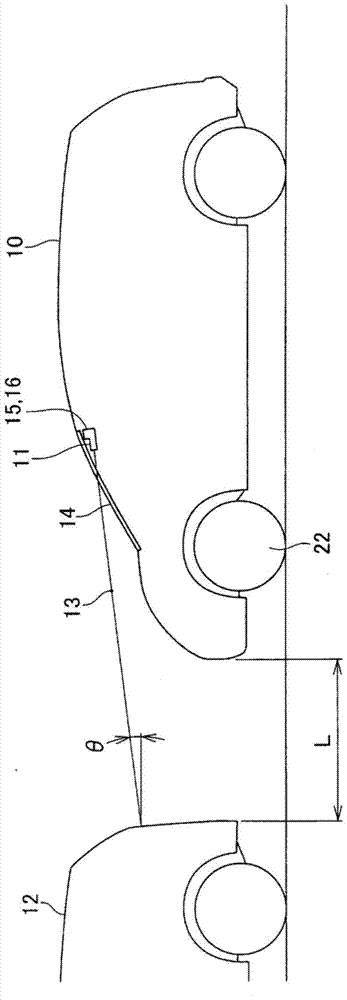
[0046] Such as figure 1 As shown, vehicle 10 has a laser distance meter 11 . The laser distance meter 11 can be used to irradiate the laser 13 to the preceding vehicle 12 to measure the inter-vehicle distance L between the vehicle (own vehicle) 10 and the preceding vehicle 12 . The optical axis angle θ formed by the optical axis of the laser beam 13 and the horizontal axis is important, and needs to be within the reference range. The present invention relates to an optical axis angle inspection device for confirming that the optical axis angle θ is within a reference range.

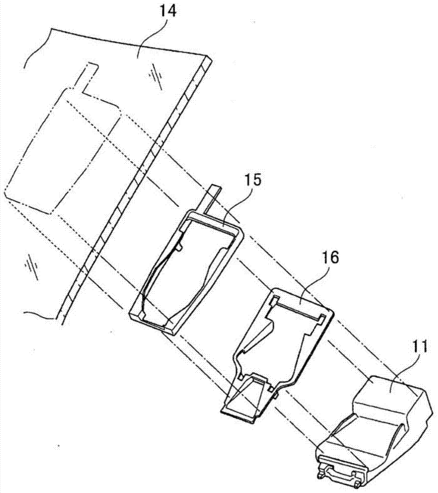
[0047] Such as figure 2 As shown, laser range finder 11 is mounted to windshield 14 of vehicle 10 using brackets 15 , 16 . The windshield 14 is curved glass, and has dimensional variations. In addition, the brackets 15 and 16 also have dimensional deviations. On this basis, the bracket 15 is adhesively fixed to the windshield 14 , so the installation angle of the laser range finder 11 inevitably de...


PUM


Abstract

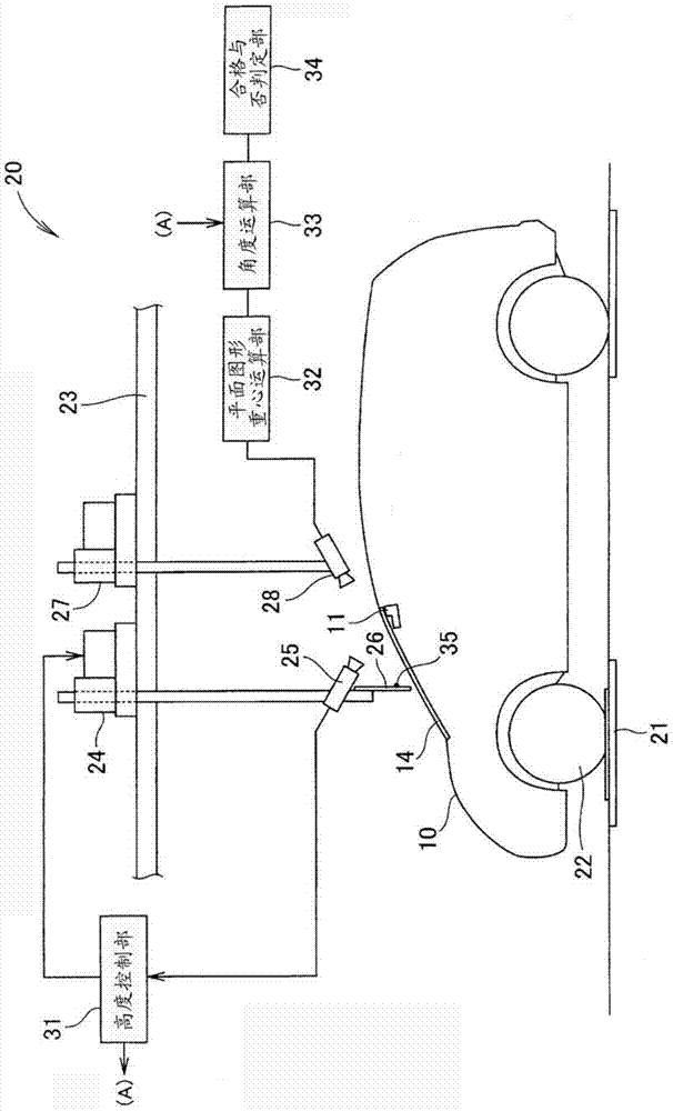
The optical axis angle inspection device (20) has a first camera (25) and a screen (26) arranged in front of the laser rangefinder (11), and a point light source (25) is arranged on the screen, and the optical axis angle inspection The device (20) has a second camera (28) arranged behind the laser distance meter (11). The laser range finder is photographed by the first camera, and the height of the point light source is matched with the height of the laser range finder based on the photographed image. Next, the point light source is photographed by the second camera, and the center of gravity of the plane figure of the photographed image and the elevation difference of the point light source are determined. Calculate the optical axis angle of the laser range finder based on the information of the elevation difference and the distance from the screen to the laser range finder.

Description

technical field [0001] The present invention relates to an optical axis angle inspection device for inspecting the optical axis angle of a laser distance meter mounted on a vehicle. Background technique [0002] In recent years, vehicles have been gradually equipped with range finders. Use the rangefinder to measure the distance between the vehicle and the vehicle in front (hereinafter referred to as the vehicle in front), and check whether the inter-vehicle distance is appropriate. [0003] As one of the forms of the distance meter, there is a distance meter using laser light. The laser range finder emits laser light to the front of the vehicle and receives the reflected light to calculate the distance. [0004] Laser light has the advantage of strong linear propagation and non-diffusion. However, the laser range finder is mounted on the vehicle using a bracket. Brackets inevitably have product deviations due to manufacturing. In addition, when the bracket is attached ...

Claims


Application Information

Patent Timeline
Patent Type & Authority Patents(China)
IPC IPC(8): G01B11/26G01S7/497H04N5/232G01S17/931
CPCG05D1/024G01B11/272G01S7/4972G01S17/931G01B11/26G01C5/00
Inventor 坂本光酒井辰也平井义贵伊藤博贵小川贵之
Owner HONDA MOTOR CO LTD
Learn More