
Sliding rail support

A slide rail and front bracket technology, which is applied in the field of slide rails, can solve the problems of damage, arc-shaped structure with low bite force, looseness, etc., and achieve the effect of reducing the cost of use, not easy to loosen, and not easy to deform

Active Publication Date: 2015-04-08
雅固拉国际精密工业(苏州)有限公司
View PDF4 Cites 8 Cited by
  • Summary
  • Abstract
  • Description
  • Claims
  • Application Information

AI Technical Summary

Problems solved by technology

In the prior art, the slide grooves formed on the inner edges of the front and rear brackets are arc-shaped, and the bite force of this arc-shaped structure is relatively low, especially when the front and rear brackets are elongated. There are fewer connected parts, and the strength of the slide rail bracket is also reduced, and the weight of the server on the slide rail is all applied to the joints of the front and rear brackets, which often leads to deformation, damage or even loosening of the slide rail bracket. take off, which increases the cost of use

Method used


Image

  • Sliding rail support
  • Sliding rail support
  • Sliding rail support

Examples


Embodiment Construction

[0019] The present invention will be described in detail below with reference to the accompanying drawings and in combination with embodiments.

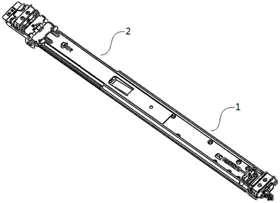
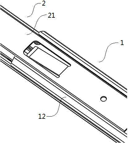
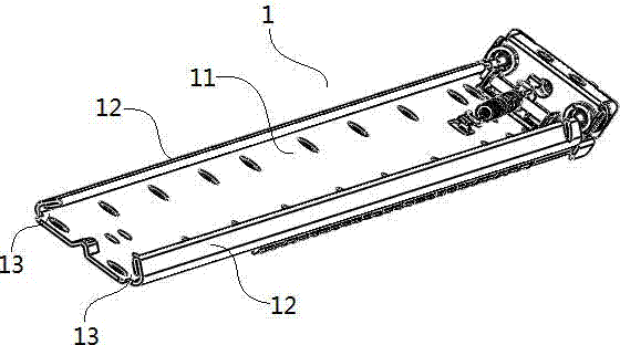
[0020] see Figure 1-5 As shown, a slide rail bracket is composed of a front bracket 1 and a rear bracket 2. The front bracket 1 includes a first main board 11, and the upper and lower edges of the first main board 11 are bent inward to form side plates. 12. The side board 12 and the first main board 11 form two triangular chute 13, the two side boards 12 have an inner splayed structure, the rear bracket 2 includes a second main board 21, and the first The edges of the upper and lower sides of the two main boards 21 are all bent inwardly to form slides 22, and the two slides 22 are in an outer splayed structure; the rear bracket 2 is movably sleeved on the slide 22 In the chute 13 of the front bracket 1, the inner splayed structure of the front bracket 1 and the outer splayed structure of the rear bracket 2 are closely matched w...


PUM


Abstract

The invention discloses a sliding rail support, which is formed by a front support and a rear support, wherein the front support comprises a first main plate; edges of the upper side and the lower side of the first main plate are bent to the inner sides to form side plates; the side plates and the first main plate form two triangular sliding grooves; the two side plates are in a toe-in type; the rear support comprises a second main plate; edges of the upper side and the lower side of the second main plate are bent to the inner sides to form sliding sheets; the sliding sheets are in a toe-out type; the rear support is movably sleeved inside the sliding grooves of the front support via the sliding sheets; and the sliding rail is fixed at the outer side of the front support. Through improvement on the sliding rail support of the prior art, the arc-shaped sliding grooves of the original front support are changed into the triangular sliding grooves, the two triangular sliding grooves form a toe-in structure, and when the sliding rail support bears a force, the toe-in structure of the front support and the toe-out structure of the rear support are closely matched, strength of the connection part between the front support and the rear support is greatly enhanced, the sliding rail support is not easy to deform and get loose, and the use cost is reduced.

Description

technical field [0001] The invention belongs to the technical field of slide rails, and in particular relates to a slide rail bracket. Background technique [0002] Slide rails for servers are usually fixed on a slide rail bracket before being installed on the server rack. In order to be suitable for server racks of different sizes, the slide rail bracket generally consists of two front and rear brackets that are sleeved together and can be adjusted in length according to needs. The front and rear brackets are respectively locked on the front and rear sides of the server rack. In the prior art, the slide grooves formed on the inner edges of the front and rear brackets are arc-shaped, and the bite force of this arc-shaped structure is relatively low, especially when the front and rear brackets are elongated. There are fewer connected parts, and the strength of the slide rail bracket is also reduced, and the weight of the server on the slide rail is all applied to the join...

Claims


Application Information

Patent Timeline
Patent Type & Authority Applications(China)
IPC IPC(8): H05K7/18
Inventor 张翔王彦民
Owner 雅固拉国际精密工业(苏州)有限公司
Learn More