
Cold heading stamping die

A stamping die and cold heading technology, which is applied in the field of molds, can solve the problems that the pressing force is not effectively buffered, the punching die is not stable, and the life of the die is low, so as to achieve the effects of increasing life, improving support stability, and reducing the fracture rate

Active Publication Date: 2017-01-04
ZHOUSHAN 7412 FACTORY
View PDF1 Cites 0 Cited by
  • Summary
  • Abstract
  • Description
  • Claims
  • Application Information

AI Technical Summary

Problems solved by technology

However, this device is only suitable for fork press molding. If the movable die is assembled with a punch rod for punching operation, the die will not be stable, and the parts will be skewed, resulting in quality accidents. At the same time, due to the huge pressing force when the parts are pressed Without effective cushioning, the life of the mold is low, so the structure of the device needs to be further improved

Method used


Image

  • Cold heading stamping die
  • Cold heading stamping die
  • Cold heading stamping die

Examples


Embodiment Construction

[0024] The present invention will be further described in detail below in conjunction with the accompanying drawings and embodiments.

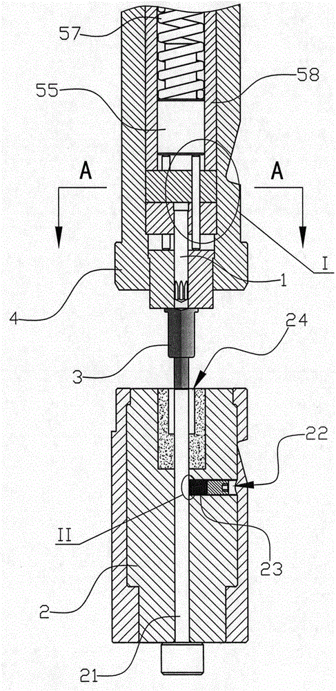
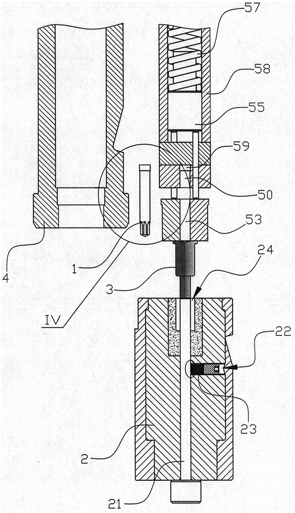
[0025] Such as Figure 1 to Figure 9 As shown, the cold heading stamping die of this embodiment includes an upper die and a lower die 2, and the lower die 2 is provided with a concave cavity that can place the stamped product 3 and is adapted to the shape of the stamped product 3, and the upper die can be relatively The lower mold 2 moves up and down, and the cavity 24 of the lower mold is vertically provided with a positioning rod 21 that can support the stamping product 3 on the top and can move up and down. The bottom of the positioning rod 21 extends out of the bottom of the lower mold 2, A horizontal jack 22 is arranged on the side of the lower mold 2, and a threaded rod that can withstand the positioning of the positioning rod 21 through friction is arranged in the horizontal jack 22. The upper mold includes a movable mold shell that can...


PUM


Abstract

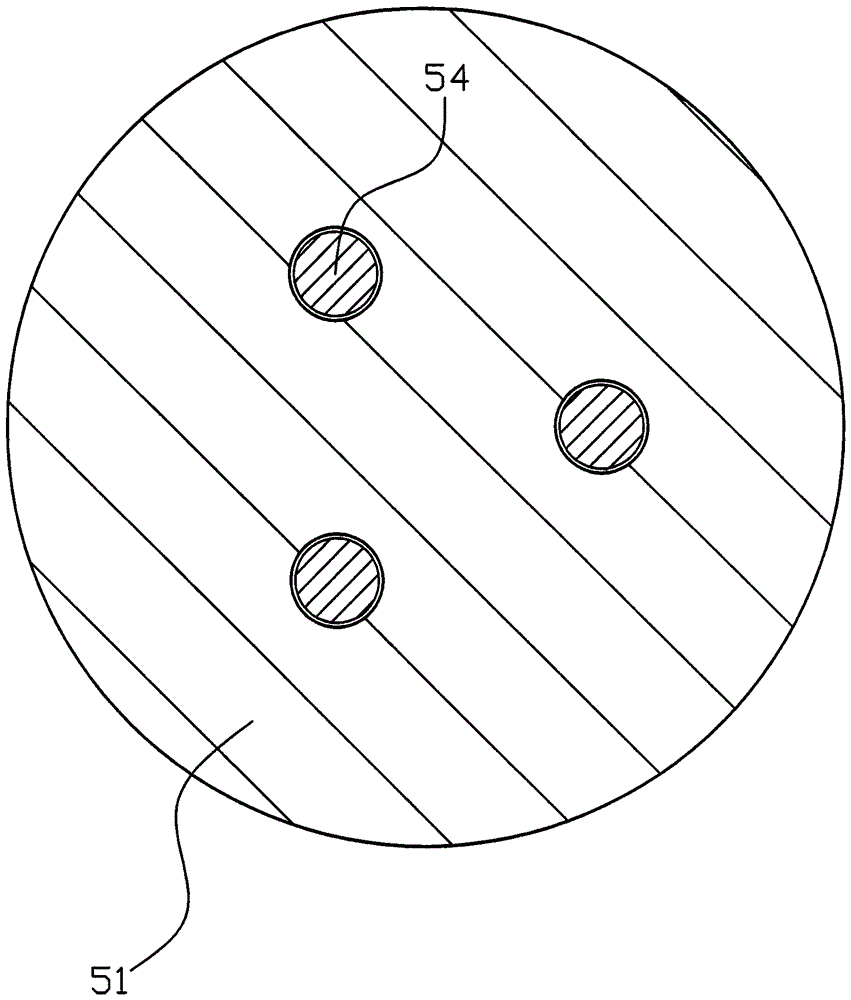
The invention provides a cold heading punching die. The cold heading punching die comprises an upper die and a lower die (2), wherein a concave cavity is formed in the lower die (2); the upper die can move up and down relative to the lower die (2); a positioning rod (21) is vertically arranged in the concave cavity (24) of the lower die; the bottom part of the positioning rod (21) extends out of the bottom part of the lower die (2); a transverse inserting hole (22) is formed in the side face of the lower die (2); a threaded rod is arranged in the transverse inserting hole (22); the upper die comprises a movable die shell (4), a die core and a punching rod (1); the die core is arranged in the movable die shell (4); the movable die shell (4) drives the die core to move up and down; the movable die shell (4) is linked with a driver; the die core comprises a punching head (5) and a punching part; the punching rod (1) can be arranged in a central hole (53) in the middle part of the punching head (5) in a manner of penetrating and vertically moving up and down; the punching rod (1) can stretch out of the bottom surface of the punching head (5) and retract into the bottom surface of the punching head (5); the punching part drives the punching rod (1) to move up and down and a buffering mechanism is arranged in the punching part. The cold heading punching die has the advantages of high punching stability, long die service life, low breaking rate of the punching rod and safety and reliability.

Description

technical field [0001] The invention relates to a die, in particular to a cold heading stamping die used for pressing parts. Background technique [0002] There is an existing Chinese utility model patent with the application number CN201120204327.2 titled "Cold Heading Die for Automobile Brake Disc Shift Fork", which discloses a cold heading die for automobile brake disc shift fork, which consists of a bottom die and a moving die. , the bottom mold includes an outer mold sleeve, a mold pad and a mold core, the outer mold sleeve is composed of an upper sleeve and a lower sleeve that are threaded, the port of the upper sleeve is provided with a mold core, and the two are fixedly sleeved, and the mold pad is formed by the lower sleeve. The sleeve is pressed and fixed in the upper sleeve, and the mold pad is close to the bottom surface of the mold core. The mold core has a mold cavity with the same shape as the head of the shift fork workpiece and a guide hole for the ejector r...

Claims


Application Information

Patent Timeline
Patent Type & Authority Patents(China)
IPC IPC(8): B21J13/02
CPCB21J13/02
Inventor 张理锋王循明夏盛斌赵萍丽
Owner ZHOUSHAN 7412 FACTORY
Learn More