
Swing Rivet Device

A swinging and riveting technology, which is applied in the field of heavy objects to press down materials, can solve the problems of small riveting impact force, long action vector, riveting failure, etc.

Active Publication Date: 2018-06-29
重庆捌益捌科技有限公司
View PDF5 Cites 0 Cited by
  • Summary
  • Abstract
  • Description
  • Claims
  • Application Information

AI Technical Summary

Problems solved by technology

[0005] The problems of the above-mentioned device are: 1. When the motor drives the rotating rod, because the motor is connected to the main shaft fixedly connected to the rotating rod, the punch is connected to the end of the rotating rod far away from the main shaft, so according to the torque formula, the punch rotates and the effect is The longer the vector, the smaller the riveting impact force. When riveting, it is easy to cause the rivet to become loose due to insufficient riveting force, or even fail to rivet; 2. When the motor drives the punch to drive the rivet, the punch is instantly The reaction force will make the punch have a tendency to move in the opposite direction, and the punch will make the motor have a tendency to move in the opposite direction through the spindle, and the motor will receive a reverse force when it is rotating forward, which will cause damage to the motor. Certain damage will reduce the service life of the motor

Method used


Image

  • Swing Rivet Device

Examples


Embodiment Construction

[0017] The present invention will be described in further detail below by means of specific embodiments:

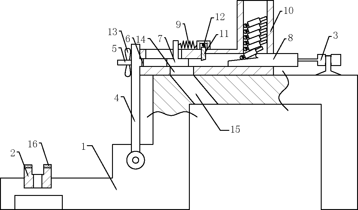
[0018] The reference signs in the drawings of the description include: frame 1, die 2, cylinder 3, rotating rod 4, punch 5, backing plate 6, impact block 7, push block 8, tension spring 9, hopper 10, pressure plate 11 , Compression spring 12, blade 13, feed hole 14, discharge hole 15, buffer rubber pad 16.

[0019] Example basic reference figure 1 Shown: a swing-type rivet device, including a frame 1, a rotating rod 4, a punch 5 and a die 2, the rotating rod 4 is rotatably connected to the frame 1, the punch 5 is rotatably connected to the rotating rod 4, and the punch 5 The blade 13 is welded on the top, the die 2 is fixed on the frame 1, the die 2 is located on the swing track of the punch 5, the die 2 is located below the punch 5, and the upper end of the die 2 is bonded with a buffer rubber pad 16, The frame below the die is connected with a riveting seat by bolts, ...


PUM


Abstract

The invention discloses a swing type rivet device. The swing type rivet device comprises a rack, a rotating rod, a male die and a female die; the rotating rod is rotatably connected to the rack, the male die is fixed to the rotating rod, the female die is fixed to the rack, the female die is located on the swing locus of the male die, a torsional spring is connected to the position where the rotating rod is rotatably connected to the rack, the position, where the rotating rod is away from the female die, of the rack is connected with an impact mechanism, and the position, opposite to the male die, of the rotating rod abuts against the output end of the impact mechanism. Compared with the prior art, the rivet device has the beneficial effects that the impact mechanism is used for directly applying force to the position, corresponding to the rotating rod, of the male die, riveting impact force of the male die can be ensured, and a rivet can be smoothly thrown into a sheet metal part rivet hole; secondly, when the rivet is thrown into the male die, the male die bears the instant counter-acting force, the male die has the motion tendency in the opposite direction, and male die resetting is facilitated.

Description

technical field [0001] The invention relates to a device for pressing down materials by using heavy objects, in particular to a swing type rivet device. Background technique [0002] At present, the riveting process has been widely used in rice metal processing, and there are many types of riveting, mainly through the use of rivets to connect two or more parts into a whole or press riveting or riveting nuts on parts A connection method such as. [0003] As a common fixed connection method, riveting has been widely used in many fields, such as riveting of sheet metal parts, riveting of automobile leaf springs, riveting of scissors, pliers, riveting of bridge construction, etc.; in order to meet market demand, there are A large number of riveting devices have appeared, mainly including two categories: rotary riveting devices and pressure riveting devices. [0004] The riveting device commonly used in the market for riveting sheet metal parts is a rotary riveting device. The ...

Claims


Application Information

Patent Timeline
Patent Type & Authority Patents(China)
IPC IPC(8): B21J15/18B21J15/38
CPCB21J15/185B21J15/38
Inventor 王川
Owner 重庆捌益捌科技有限公司
Learn More