Medical device

A technology of medical equipment and internal space, which is applied in the fields of medical science, lighting and heating equipment, radiological diagnostic equipment control, etc., can solve problems such as limiting the possibility of lighting, and achieve the effect of avoiding image interference, easy to replace, and easy to install

Inactive Publication Date: 2015-04-01
SIEMENS AG
View PDF8 Cites 2 Cited by
  • Summary
  • Abstract
  • Description
  • Claims
  • Application Information

AI Technical Summary

Problems solved by technology

However, the installation strongly limits the lighting possibilities

Method used


Image

  • Medical device
  • Medical device
  • Medical device

Examples


Embodiment Construction

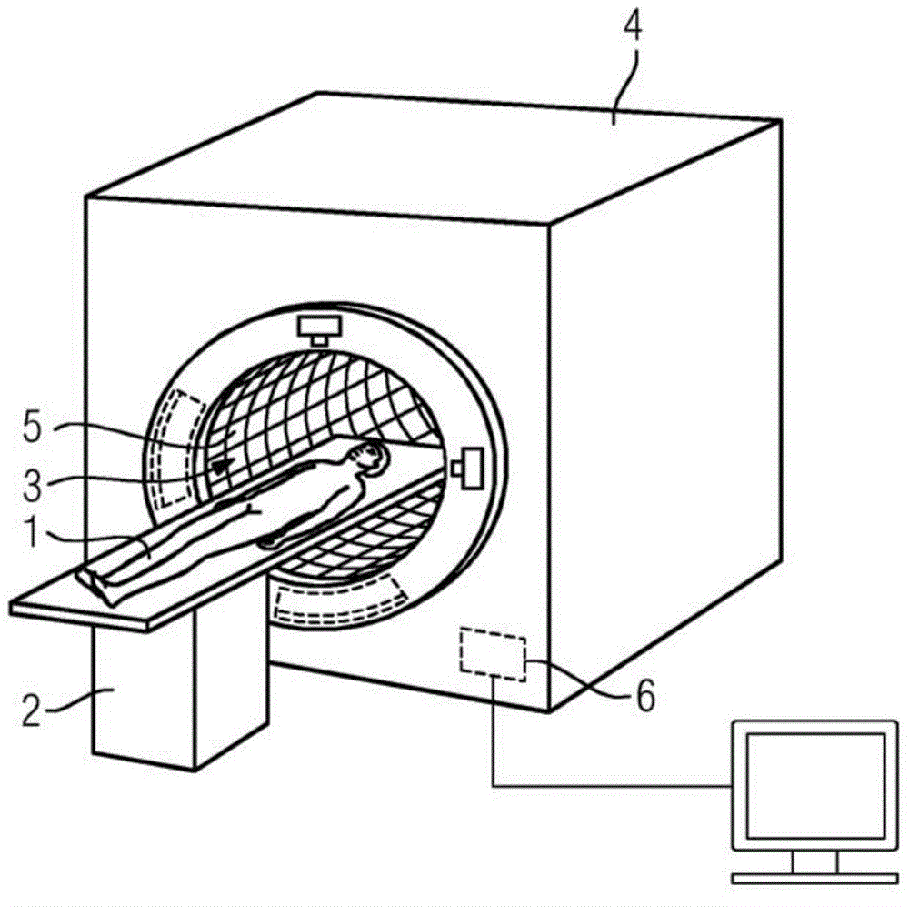
[0038] figure 1 An embodiment of the medical device is shown in a perspective view. An examination object 1 (patient) is moved into a tubular interior 3 of a medical device 4 by means of a patient positioning device 2 in the form of a patient couch. Illumination of the tubular interior 3 takes place by means of lighting elements 5 . The control of the lighting takes place via the control unit 6 .

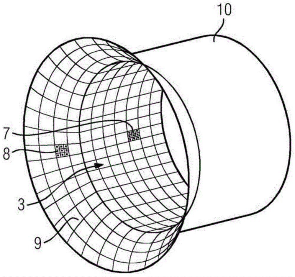
[0039] The lighting part 5 is configured as an LED tile. By using smaller pieces, it is possible to form a tubular contour and thus maintain a maximum free volume in the tubular interior 3 . Each LED block contains several individually controllable RGB-LEDs, which allow the tube-shaped interior to be illuminated in patterns and colors. Control of individual LED tiles is done digitally and through array connections between tiles. Each single LED tile contains a controller for a single mounted LED. The control unit can respond with commands, which are transmitted via the serial ...


PUM


Abstract

The invention relates to a medical device (4) with a tubular interior space (3) for accommodating the subject to be examined (1), a cladding (10) of the tubular interior space (3) facing towards the subject to be examined and a device for lighting the tubular interior space (3), which comprises at least one lamp (5), wherein the lamp (5) is mounted on the side of the cladding (10) of the tubular interior space (3) facing towards the subject to be examined and forms the tunnel contour of the tubular interior space (3).

Description

technical field [0001] The invention relates to a medical device having a tubular interior for receiving an examination object, a surface of the tubular interior facing the examination object, and a device for illuminating the tubular interior comprising at least one lighting element. Background technique [0002] In modern medicine, patient comfort is of great value. In the case of devices with a tubular interior into which the patient can be inserted, such as computed tomography or magnetic resonance tomography, this can cause discomfort for sensitive patients. Many patients have a fear of cramped and / or dark spaces. Until now, the impression of a "dark tube" could only be avoided by choosing an appropriate lighting of the examination space. For magnetic resonance tomographs, a system is also known for illuminating the tubular interior by means of LED rows in the lower tunnel region. However, this device strongly limits the lighting possibilities. Contents of the inve...

Claims


Application Information

Patent Timeline
Patent Type & Authority Applications(China)
IPC IPC(8): A61B6/03A61B5/055G01R33/28A61B6/00F21V33/00
CPCA61B6/032A61B6/54A61B5/055F21V33/0068G01R33/28A61B90/30A61B2090/309A61B2090/306A61B2562/164
Inventor H-J.米勒A.威辛格
Owner SIEMENS AG
Why Eureka
Try Eureka