
Fault simulation and test system

A fault simulation and testing system technology, applied in the direction of testing/monitoring control system, general control system, electrical testing/monitoring, etc., can solve problems such as inability to support third-party tool calls, difficult fault implementation, and many operation steps, etc., to achieve Automatic fault simulation and fault diagnosis, reduced workload, and convenient integration

Inactive Publication Date: 2015-04-01
ISOFT INFRASTRUCTURE SOFTWARE
View PDF6 Cites 30 Cited by
  • Summary
  • Abstract
  • Description
  • Claims
  • Application Information

AI Technical Summary

Problems solved by technology

[0004] In the traditional multifunctional system of fault simulation and testing, the fault is mainly injected into the device first, and the fault is triggered manually or by a relay, and then other devices or corresponding diagnostic instruments are used for diagnosis; this makes certain triggering conditions more difficult. Harsh faults are difficult to achieve, and the operation steps of the entire testing process are both numerous and complex. At the same time, the above-mentioned fault injection equipment cannot support the invocation of third-party tools, resulting in low reuse rate and poor test accuracy.

Method used


Image

  • Fault simulation and test system
  • Fault simulation and test system
  • Fault simulation and test system

Examples


Embodiment Construction

[0027] The specific embodiment of the present invention will be further described below in conjunction with accompanying drawing:

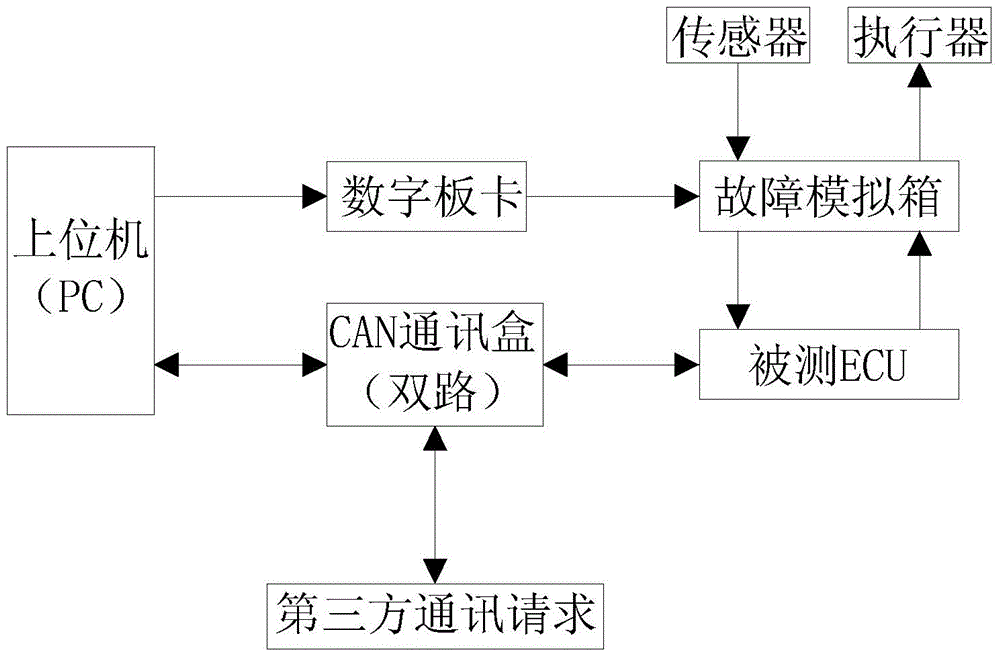
[0028] figure 1 It is a schematic structural diagram of the fault simulation and testing system in the embodiment of the present application; as figure 1 As shown, a fault simulation and testing system in this embodiment includes a host computer (such as a PC, etc.), a digital board, a fault simulation box, a CAN (Controller Area Network, controller local area network) communication box, etc., and the host computer passes through a digital board Connect with the fault simulation box to drive the digital board to control the fault simulation box to perform fault simulation operations on the above-mentioned ECU under test, and the host computer is also connected to the above-mentioned On the ECU under test, after performing the above fault simulation operation on the ECU under test, drive the CAN communication box to perform fault diagnosis on the ...


PUM


Abstract

The invention relates to a fault simulation and test system and belongs to the automobile electronic exploitation and test technology field. Automatic simulation and automatic diagnosis on multiple types of faults of each signal path can be realized through setting a host computer and the corresponding fault simulation and diagnosis equipment and further through utilizing preset fault simulation and diagnosis data, an external communication request can be further realized through utilizing a CAN communication box to carry out fault simulation and diagnosis on a detected ECU, so automatic fault simulation and automatic fault diagnosis can be realized, integration with a third-party test system can be conveniently realized, artificial test workload and professional level requirements for testers can be reduced, and thereby fault simulation and diagnosis cost is greatly reduced, and a tool utilization rate and test accuracy can be effectively improved.

Description

technical field [0001] The invention relates to the technical field of automotive electronics development and testing, in particular to a fault simulation and testing system. Background technique [0002] At present, because the electronic control unit (Electronic Control Unit, referred to as ECU) multifunctional system for fault simulation and testing can simulate and test various faults of ECU, it is widely used in the development process of ECU to effectively verify the design Whether the products that come out meet the previous design requirements. [0003] In the field of automotive electronics research and development and testing, since the fault diagnosis of ECU is the key technology, the corresponding fault diagnosis test is particularly important; the above-mentioned fault diagnosis test is mainly through all the predefined faults one by one Carry out simulation, and send corresponding diagnostic service commands to the ECU under test according to the diagnostic pr...

Claims


Application Information

Patent Timeline
Patent Type & Authority Applications(China)
IPC IPC(8): G05B23/02
CPCG05B23/0256
Inventor 江水张晓先王琴顾运孙文圣
Owner ISOFT INFRASTRUCTURE SOFTWARE
Learn More