Box body interlayer water-cooled type small-tooth-difference reducer box of heavy duty plate feeder

A technology of apron feeder and reduction box, which is used in mechanical equipment, gear transmission, gear lubrication/cooling, etc. Effect

Inactive Publication Date: 2015-04-01
吴小杰
View PDF5 Cites 0 Cited by
  • Summary
  • Abstract
  • Description
  • Claims
  • Application Information

AI Technical Summary

Problems solved by technology

[0017] The purpose of the present invention is to solve the defects of too long transmission chain and low thermal power in the prior art, provide a small tooth difference transmission with an additional modular internal meshing gear pair, the transmission chain is shortened to two stages, and natural heat dissipation is replaced by water cooling in the interlayer of the box body, so that The thermal power can approach or reach the rated mechanical power, a box interlayer water-cooled heavy-duty apron feeder gear box with less tooth difference

Method used


Image

  • Box body interlayer water-cooled type small-tooth-difference reducer box of heavy duty plate feeder
  • Box body interlayer water-cooled type small-tooth-difference reducer box of heavy duty plate feeder
  • Box body interlayer water-cooled type small-tooth-difference reducer box of heavy duty plate feeder

Examples


Embodiment Construction

[0042] The present invention is described in detail below in conjunction with accompanying drawing:

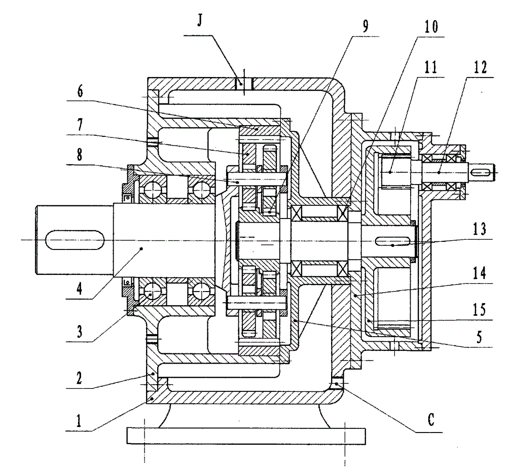
[0043] refer to figure 1 . A box interlayer water-cooled heavy-duty apron feeder gear box with less tooth difference, comprising a box body 1 and an input shaft 13 arranged in the box body 1 and sequentially driven, a transmission mechanism and an output shaft 4, characterized in that:

[0044] The box body 1 is provided with a connecting piece between the inner cylinder 2 and the round end cover 5, the flange of the inner cylinder 2 is connected to the output end surface of the box body 1, and the outer circle of the input end of the round end cover 5 is connected to the box body. The inner hole of the input end of the body 1 is tightly matched, and the input end faces of the round end cover 5 and the box body 1 are sealed and connected with the end face of the modular round shell 14 at the same time, and the connection between the built-in cylinder 2 and the round end cover ...


PUM


Abstract

The invention relates to the improvement of DT type feeder reducers, particularly to a box body interlayer water-cooled type small-tooth-difference reducer box of a heavy duty plate feeder. The box body interlayer water-cooled type small-tooth-difference reducer box comprises a box body, an input shaft, a transmission mechanism and an output shaft, wherein the input shaft, the transmission mechanism and the output shaft are arranged in the box body. The box body interlayer water-cooled type small-tooth-difference reducer box is characterized in that a connecting part of an inner cylinder and a circular end cover is arranged in the box body; the inner cylinder is connected with an output end of the box body; an outer circle of an input end of the circular end cover is in interference fit with an inner hole formed at an input end of the box body; the input end of the circular end cover is connected with the input end of the box body through a circular casing in a sealing mode; the inner wall of the box body and the outer wall of the connecting part of the inner cylinder and the circular end cover form an interlayer; a water inlet valve and a water outlet valve are arranged at the top and on the lateral portion of the box body respectively; the input shaft and the output shaft are supported in the circular end cover and the inner cylinder through a bearing respectively; the transmission mechanism comprises a planetary gear, an inner gear ring, an eccentric bearing and a cylindrical pin; an inner meshing pair is arranged in the circular casing and comprises an inner gear ring and a small gear. According to the box body interlayer water-cooled type small-tooth-difference reducer box of the heavy duty plate feeder, the heat of an interlayer water sleeve is discharged from the water outlet valve and emitted out of the box body, the water can be adjusted to increase the heat efficiency, a main box body is unchanged, and only the inner meshing gear pair speed ratio needs to be changed to obtain a series of products.

Description

【Technical field】 [0001] The present invention relates to the improvement of the prior art DT heavy-duty apron feeder combined suspension special reducer (abbreviated as DT-type feeder reducer), and specifically relates to a water-cooled heavy-duty apron feeder gear box with a small tooth difference between the box interlayers . 【Background technique】 [0002] Apron feeders are widely used in crushing and grading workshops of large-scale mineral processing plants, as continuous or uniform feeding from self-storage silos to primary crushers, and as short-distance transport for reloading. For example, it is used to directly feed ore into large vehicles at the bottom of the mine shaft, and it is used to continuously and evenly feed and load each truck from the raw material warehouse. [0003] DT type feeder reducer is a special reducer successfully designed by the Transmission Machinery Research Institute of NHI with reference to the technology of Flender, Germany. It adopts a...

Claims


Application Information

Patent Timeline
Patent Type & Authority Applications(China)
IPC IPC(8): F16H1/28F16H57/04
CPCF16H1/32F16H57/032F16H57/0412F16H57/0417F16H2001/327
Inventor 吴声震
Owner 吴小杰
Why Eureka
Try Eureka